Categories
Manufacturing

Custom Metal Machining Solutions For Industrial Applications in Dallas

Surprising fact: more than 70% of critical industrial failures can be traced to a single part that drifted বাইরে tolerance by less than 0.5 mm. Lowrance Machine delivers precision-driven Lowrance Machine Dallas solutions designed to reduce that risk. We rely on proven machining methods and strict inspection procedures to keep parts within strict tolerances. This reduces downtime, supports consistency, and strengthens production reliability for U.S. manufacturers.

Custom Metal Machining Solutions For Industrial Applications in Dallas
With deep experience in custom component work, we produce components and products that fit each client’s operating environment. Explore www.lowrancemachine.com to learn how our experienced team and precision equipment produce reliable parts that meet engineering specifications and support your production goals.

Important Takeaways

  • Precision components reduce expensive failures and keep lines running smoothly.
  • Lowrance Machine Dallas Services emphasize tolerance control and repeatability.
  • Experienced staff apply advanced machining methods to produce dependable products.
  • All parts are checked carefully to ensure compliance with demanding engineering requirements.
  • Visit www.lowrancemachine.com to review tailored solutions for your production needs.

Precision Engineering Inside Lowrance Machine

In our shop, precision engineering transforms detailed drawings into dependable parts. We focus on strict dimensional control and repeatable processes so every finished part matches the assembly it was designed for.

Quality is not just a label here; it is a daily discipline. Our team combines practical experience with calibrated equipment to meet the needs of each business we serve.

  • Tailored solutions designed around project scope and production timing.
  • Routine inspections that support dependable product quality for every customer.
  • Experienced machinists who apply years of knowledge at every station.
  • Explore www.lowrancemachine.com to see how our service can strengthen production uptime.

Our shop offers straightforward communication, fast turnaround, and engineered answers that reduce operational risk. Partnering with us means receiving parts that perform when you need them most.

Lowrance Machine Precision Machining in Dallas

Comprehensive Lowrance Machine Dallas Services

Our company provides a full range of precision machining services designed to help you meet production targets. You can call (281) 449-6524 or visit www.lowrancemachine.com to talk through schedules, pricing, and project details.

Over the years, we have refined our processes to handle diverse materials and complex components. That experience helps customers shorten lead times, reduce rework, and improve output consistency.

Quality is monitored through strict metrics that resemble the disciplined reporting systems used by regulated organizations. This focus supports consistent output, tighter control, and predictable results for your operation.

Reach out through www.lowrancemachine.com to find out how our machining services can support your toughest production demands.

Advanced CNC And Manual Machining Capabilities

By combining CNC accuracy with hands-on manual skill, we can handle complex components with confidence. That hybrid method gives us both production speed and fine control on demanding work.

We rely on advanced cnc manual workflows to make sure each component meets drawing tolerances. That means blending programmed accuracy with expert manual setup for repeatable, high-precision results.

Our machine shop works with many materials, including aluminum, stainless steel, and engineering plastics. That flexibility allows us to produce molds, prototypes, and production components to specification.

Go to www.lowrancemachine.com to review how our CNC manual workflow delivers flexible machining solutions across different sectors.

Inside our modern facility, manual craftsmanship and advanced machine controls operate side by side. The benefit is shorter lead times, better first-run success, and more dependable overall output.

Machining Capability Materials Typical Output
CNC turning & milling Aluminum, steel, brass Molds and close-tolerance components
Manual setup & finishing Plastics, composites Prototypes, low-volume runs
Inspection & QA Every supported material Measured parts, certified lots
  • Combined CNC and manual workflows for complex geometries and tight tolerances.
  • Broad material support to match design requirements and real-world performance goals.
  • Explore www.lowrancemachine.com for examples of our work and direct contact details.

Commitment To Quality And Innovative Design

We combine creative engineering with measurable quality controls to produce parts that perform reliably. This balance allows us to support both design goals and manufacturing demands.

Lowrance Machine creates thoughtfully designed and engineered products in many sizes and configurations. Each finished product is intended to give businesses dependable fit, proper function, and long service life.

Our company draws on years of experience to expand design capability and serve diverse customer requirements. Our investment in talent and tools helps customers receive stronger quality outcomes.

Visit www.lowrancemachine.com to review examples of our work and see how quality shapes every product we manufacture.

Equipment And Processing Techniques In Our Shop

Our shop embraces newer processing methods so every job is matched with the proper tooling, setup, and workflow. Lowrance Machine invests in current systems to provide fast, precise work and practical solutions across industries.

Our machine shop blends advanced cnc centers with skilled manual setups. That mix helps us produce high-quality molds and parts on demanding timelines.

Each machine is calibrated and maintained to preserve tolerance accuracy. We follow validated workflows to help hit quality targets on the first pass.

“When we invest in proper tools and methods, our clients gain consistent and measurable results.”

  • Modern shop floor equipped with calibrated tools and maintained systems.
  • A hybrid CNC-manual process designed for repeatability and part consistency.
  • Open project details and examples can be found at www.lowrancemachine.com.
Equipment Type Typical Process Typical Production Output
CNC mills & lathes Automated runs and programming Close-tolerance components
Manual machining stations Finishing & setup Prototype jobs and low-volume molds

Serving Diverse Industry Requirements

We support manufacturers with quality parts and products designed to solve real production challenges. Our service model emphasizes clear communication and delivery performance that customers can plan around.

Lowrance Machine adapts its machining capabilities to meet the needs of different industries. That includes working with a wide range of materials to create prototypes, molds, and durable production components.

“We fine-tune every production run so customers get the right part, on schedule, and to the exact spec they count on.”

  • Adaptable machining support for prototype work as well as higher-volume production.
  • Material expertise that matches process selection to component requirements.
  • Responsive customer service built to fit project-specific production constraints.
Industry Common Materials Used Typical Result
Aerospace Stainless steel and aluminum Close-tolerance components
Medical sector Titanium and plastics High-precision molds and components
Industrial sector Alloy steels, composites Durable production products

Explore www.lowrancemachine.com to review how our service-oriented approach and optimized setups help manage complex, demanding projects in the Dallas area.

Partnering With Our Dallas Machining Experts

Choose a machining partner that provides clear planning and practical solutions to keep production moving. The benefit is reduced downtime, better part consistency, and stronger overall production performance.

Our company-run machine shop combines CNC capability with experienced manual skill. We offer a professional service built around timely quotes, quality checks, and efficient workflows.

Working with Lowrance Machine gives your business access to extensive experience and tailored machining services at www.lowrancemachine.com. We work to become a trusted partner for today’s projects and tomorrow’s growth.

Visit www.lowrancemachine.com to discuss how our machining team can help your business achieve its goals with reliable, precision-focused solutions.

Categories
Manufacturing

Cleanliness Protocols for a Fiber Coloring Machine

Is It Possible That the machines manufacturing fiber optic cable production machinery act as the unseen force that ultimately delivers true gigabit access to every American home? This article delves into the recent breakthroughs in FTTH Cable Production Line Technology. These advancements are revolutionizing broadband network infrastructure and advancing fiber to the home technology across the United States.

Fiber Cable Sheathing Line

Fiber Draw Tower

Fiber Draw Tower

Modern advancements in automation, precision engineering, and AI-driven inspection are greatly cutting production costs and boosting quality. This synergy makes high-speed internet technology more reliable and simpler to implement for service providers and municipalities.

Global optical cable output now exceeds hundreds of millions of kilometers annually. This surge is powered by 5G deployments, hyperscale data centers, and the growing demand for streaming and remote work. The subsequent sections will examine automation and Industry 4.0, the use of low-loss materials, AI quality control, innovative cable designs such as bend-insensitive fiber and flat drop microcables, and the pursuit of sustainability in production lines.

Telecommunications manufacturing, network planning, and procurement professionals will discover valuable insights. These insights focus on selecting the right fiber optic cable production machinery and optimizing processes. They are designed to meet regional deployment needs and future bandwidth growth.

FTTH Cable Production Line Technology

The term encompasses the machinery, control systems, and materials transforming optical preforms into deployable fiber cables. It covers fiber drawing and coating, SZ stranding, ribbon formation, extrusion of jackets, armoring, taping, automated testing, and final take-up systems. Each step’s precise control defines the fiber optic cable production process, ensuring consistent performance.

The manufacturing chain demands stringent tolerances. SZ stranding systems align dozens of strands with micron-level tension precision. Extrusion lines employ servo-driven extruders and laser micrometers to maintain jacket thickness within ±0.02 mm. Such precision minimizes variability, lowering attenuation and making field splicing easier.

Standards and regulatory frameworks strongly shape manufacturing decisions. Compliance with ITU-T recommendations, such as G.657, and regional fire codes like CPR in Europe, is essential. Meeting these standards ensures products align with the broader broadband network infrastructure.

Quality in production directly impacts network economics and service delivery. Lower attenuation and consistent geometry reduce splice loss and extend reach. This enhances reliability for carriers, ISPs, and utilities, while lowering the total cost of ownership for FTTH deployments. The growing demand for symmetrical multi-gigabit services, 5G backhaul, and data center interconnect is driving the scale-up of modern lines.

Comparing key process components and tolerances reveals their impact on output and quality.

SZ Stranding Line

Process Component Typical Control Impact on Performance
Fiber draw and coating ±1°C temperature control; coating concentricity ±5 µm Stable geometric profile; lower macrobend loss
Ribbon formation and SZ stranding Micron-level tension regulation; synchronization at 0.5 ms Even fiber pitch; more predictable connector and splice results
Jacket extrusion and thickness control Laser micrometer feedback; tolerance of ±0.02 mm Consistent mechanical protection; predictable installation behavior
Armoring & taping Servo feed management; alignment control of layers Improved crush resistance; compliant aerial/underground specs
Automated testing and take-up Line-speed OTDR and insertion-loss checks; tension-controlled winding Complete quality traceability; lower rework and fewer failures in the field

Manufacturers like Corning, Prysmian Group, and Sumitomo Electric focus on tighter process control to meet operator expectations. Continuous advancements in the fiber optic cable production process enable networks to scale while maintaining performance in the last mile of broadband network infrastructure.

Automation And Industry 4.0 In Fiber Optic Cable Production

Factory floors for fiber optic cable production machinery now mirror advanced manufacturing plants from other industries. Smart controls, synchronized stages, and data-driven decision making raise output and protect quality. These shifts shorten commissioning time for new product families. They let telecommunications equipment manufacturers pivot between armored aerial lines and microcable runs with minimal downtime.

Smart machinery and PLC integration

Programmable logic controllers coordinate stranding frames, ribbon formers, and take-up units to keep tension within sub-0.01mm windows. Servo-driven extrusion coupled with laser micrometers enforce ±0.02mm jacket thickness. The result is fewer rejects, less rework, and consistent optical performance on every reel.

Edge computing and production orchestration

Local edge servers ingest terabytes of telemetry each day. They drive low-latency closed-loop adjustments and push immediate alerts when deviations occur. This approach keeps optical fiber cable equipment running at peak efficiency. It supports real-time quality assurance during long production runs.

AGVs, material flow, and workflow gains

Automated Guided Vehicles move heavy cable drums with millimeter-level repeatability. Laser-navigated AGVs reduce manual handling injuries and speed material flow between extrusion, curing, and drum stations. This automation lowers labor costs while raising throughput on ftth cable production line technology setups.

Benefits for makers and the supply chain

  • Greater throughput with repeatable outcomes
  • Faster prototyping and shorter time to market
  • Reduced labor exposure and lower operating cost
  • Improved integration between optical fiber cable equipment and enterprise systems

Industry adoption and ecosystem trends

Leading telecommunications equipment manufacturers pair PLCs with robotic arms, AGVs, and industrial IoT stacks to reach Industry 4.0 goals. This integration creates a resilient production base. It is able to adapt as demand shifts toward denser, more complex FTTH offerings.

Precision Engineering Breakthroughs For Lower Attenuation

Advances in materials and mechanical design are driving down loss in modern fiber lines. Engineers pair ultra-low loss fiber with tighter coating control to reduce intrinsic and bending attenuation. These gains matter to network operators who want longer spans and fewer amplifiers in high-speed internet technology deployments.

The fiber optic cable production process now favors smaller coated diameters such as 180µm and 160µm. These sizes let manufacturers increase fiber count and build denser microcables without sacrificing handling or optical stability.

Low-Loss Glass And Advanced Coatings

Manufacturers use improved glass formulations that lower Rayleigh scattering and reduce baseline attenuation. Ultra-low loss fiber variants extend reach for long-haul and high-capacity links while easing repeaters and amplifier requirements.

Coating chemistry has progressed too. UV-cured acrylate systems cut microbending loss by roughly 40% compared with earlier generations. That performance drop helps maintain signal integrity in cramped ducts and tight bends common in FTTH and 5G backhaul networks.

Central Strength Members And Mechanical Design

Mechanical design updates center on robustness and dimensional control. Fiber-reinforced plastic (FRP) rods with tensile strengths near 1.2 GPa serve as central strength members. They limit elongation during pulling and boost crush and bending resilience.

Water-blocking advances use swellable yarns and grease-free gel compounds to achieve near-complete moisture resistance. These measures protect optical paths and raise in-service reliability for cable installations in challenging environments.

These precision engineering steps integrate directly into fiber optic cable manufacturing workflows. When the production line aligns glass, coating, and mechanical specs, attenuation falls and networks gain reliability. That alignment shortens time to service for operators deploying modern broadband and high-speed internet technology.

Quality Control 4.0 And AI-Powered Inspection

Smart factories for fiber optic cable production now embed inspection systems that run continuously. These systems combine machine vision, machine learning, and automated testers to watch every reel and spool. The result is tighter feedback during the fiber optic cable production process and fewer surprises in the field.

AI models score coating uniformity, microbends, and surface defects at line speed. They cross-reference process telemetry from fiber optic cable production machinery and predict deviations hours before a reel moves to final spooling. This allows for in-line adjustments without stopping the line.

Automated OTDR integration performs 100% attenuation testing on every length. Modern OTDR systems using 1550nm sources map loss across reels and flag changes as small as 0.01 dB/km. Inline OTDR logs feed edge analytics for rapid root-cause tracing when a batch shows anomalies.

Robotic bend-radius simulators apply repeated stress cycles while monitoring macrobend loss. These testers validate compliance with ITU-T G.657 and customer bend specifications by running controlled bends at multiples of the cable diameter. Test outcomes are tied to batch IDs for traceability.

Thermal cycling chambers stress jackets and splices across wide temperature ranges. Environmental tests up to +85°C and down to -60°C confirm stability for extreme climates. Automated logs record each chamber run and link results to production lots.

Quality control 4.0 reduces returns and field failures by making 100% in-line testing routine. Edge analytics and OTDR integration shorten diagnosis times and improve regulatory compliance. Broadband operators see fewer truck rolls and better lifecycle performance for FTTH networks.

Cable Design Innovations For FTTH Deployments

New cable designs address common field challenges in fiber to the home technology. Engineers focus on durability, space economy, and speed of activation. These trends reduce installation time and lower long-term operational costs.

Bend-Insensitive Fiber Benefits For MDUs And Tight Routing

Bend-insensitive fiber maintains signal strength when routed around corners and through confined spaces. ITU-T G.657 compliant fibers minimize attenuation at tight radii, protecting links in multi-dwelling units and behind baseboards. Prysmian’s BendBright family and BendBrightXS exemplify how smaller coated diameters facilitate routing without compromising optical performance.

Flat Drop And Microcable Options For Flexible Deployments

Flat drop cable remains a preferred choice for aerial self-support, duct installs, and direct burial in North America. Its profile accommodates narrow pathways and enhances aerial spans with appropriate clamps. High-fiber-count flat drops necessitate enhanced radial strength and more robust hardware for longer spans.

Microcable technologies reduce outside plant profiles to 8 mm or less. Microcables and air-blown systems enable capacity addition inside existing ducts and congested corridors. These approaches reduce civil works, lower labor costs, and facilitate incremental network growth for urban and campus builds.

Pre-Connectorized Solutions To Speed Field Activation

Pre-connectorized solutions offer factory-terminated, plug-and-play assemblies that minimize field fusion and connector errors. Hardened outdoor connectors and vendor offerings like Prysmian’s ezDROP simplify mass rollouts and enhance first-pass yield. Service teams experience fewer truck rolls and faster service turn-up for smart city and 5G edge projects.

Design Type Core Advantage Common Use Case Deployment Factor
BIF Reliable operation at tight bend radii Multi-dwelling units, indoor routing, compact pathways Choose ITU-T G.657 variants for indoor runs
Flat drop fiber cable Multiple deployment modes Aerial service drops, direct burial, duct installs Apply suitable clamps and radial-strength hardware
Microcable solutions Minimal footprint, incremental capacity Microduct installs, congested urban ducts Air-blown systems need compatible blower tools
Pre-connectorized solutions Quicker field activation with fewer errors Mass rollout projects and fast turn-up Prepare for standardized connector interfaces

Sustainability And Energy Efficiency In Production Lines

Manufacturers in the fiber optic cable industry are embracing greener practices to reduce costs and meet consumer demands. Facilities prioritizing sustainable production witness improvements in operational efficiency and brand reputation. These advancements impact power systems, cooling, raw materials, and waste management.

Power recovery strategies are becoming prevalent on extrusion lines and take-up reels. Regenerative braking on motor-driven spools returns power to the grid, thereby lowering net consumption. Studies indicate that energy recovery can reduce drive energy use by up to 32 percent in retrofitted reels.

Closed-loop cooling and chiller-less extrusion systems are reducing water demand. Adiabatic cooling can decrease water use by as much as 75 percent, particularly beneficial in water-scarce areas. Plants employing closed-loop cooling systems, in conjunction with heat exchangers, maintain temperature control while reducing utility expenses.

Recyclable jacket materials are transforming the disposal of cables. New polypropylene-based and modified polymer compounds meet mechanical and fire-safety standards, enabling higher recycling rates. Suppliers like Borealis and LyondellBasell are developing compounds that support the circular economy in cable jackets.

Process optimization minimizes scrap before recycling. Precision extrusion, in-line laser measurement, and real-time analytics reduce off-spec runs. Digital twins enable engineers to refine parameters, enhancing batch yields and reducing material waste.

Regulatory pressures and corporate ESG goals are compelling operators to favor vendors with transparent sustainability metrics. Municipal procurement teams and large network operators increasingly consider lifecycle impacts when selecting suppliers.

Area Common Improvement Main Benefit
Regenerative reel drives Energy reduction up to 32% Lower power costs and less peak demand
Closed-loop cooling and adiabatic systems Roughly 75% less water use Lower water expenses and better compliance in arid areas
Recyclable jacket materials Higher post-consumer recycling rates Improved circularity and easier end-of-life handling
In-line inspection and digital twins Double-digit cuts in scrap and off-spec runs Improved yields with less wasted material
Reporting and sustainability certifications Better standing in procurement A competitive edge with network operators

Implementing these measures enhances the resilience of fiber optic cable manufacturing. It leads to lower lifecycle costs and easier compliance. Manufacturers integrating energy recovery and recyclable jacket materials position themselves for growth in the green procurement market.

Emerging Technologies Shaping Cable Manufacturing

New technologies are transforming the design and operation of fiber optic cable production machinery. These innovations expedite commissioning, diminish prototyping cycles, and empower manufacturers to test process alterations without halting production.

Digital twins create virtual replicas of entire production lines and novel cable designs. Engineers at Corning and Prysmian leverage these models to validate footprint, material flow, and layout before physical construction. Studies indicate commissioning can be up to 60% swifter when teams execute virtual scenarios and optimize layouts beforehand.

Digital twins facilitate expedited R&D for bespoke items such as armored variants and anti-rodent jackets. Virtual testing minimizes the necessity for physical prototypes and accelerates market entry. Teams can simulate process modifications, observe material interactions, and refine equipment parameters in a risk-free milieu.

AI systems introduce predictive capabilities on the factory floor. Machine learning scrutinizes 50+ parameters to forecast failures and quality deviations hours in advance. This AI predictive maintenance lessens unplanned downtime and elevates overall equipment effectiveness for high-volume lines.

Manufacturers like Siemens and ABB integrate AI with edge computing, enabling models to operate proximal to machines. Alerts prompt targeted inspections, spare part staging, and corrective actions before a fault halts production. This strategy maintains yield and shortens mean time to repair.

Quantum fiber sensing and distributed monitoring extend capabilities beyond production to the deployed cable. Embedded Brillouin and distributed acoustic sensing provide continuous strain and temperature data across extensive spans.

Integration of quantum fiber sensing enhances network diagnostics and supports structural health monitoring. Field teams acquire actionable insights when sensing data is linked to manufacturing records and test logs. This connection enables tracing anomalies to specific production batches.

Combined workflows—digital twins plus AI predictive maintenance—accelerate both commissioning and product development. Manufacturers embracing these tools can respond more swiftly to market fluctuations and deliver higher-value, differentiated cables.

Market-Driven Production Adaptations And Regional Needs

The global demand for fiber access compels manufacturers to adapt their production lines to local requirements. Regional fiber optic cable manufacturing now emphasizes durability, density, and safety. Plants employ modular equipment, enabling swift transitions between product families and meeting specific operator needs without significant delays.

In North America, networks predominantly opt for aerial routes and robust outside-plant solutions. Producers concentrate on creating armored aerial cables with enhanced breaking strength, corrosion-resistant armor, and simplified pole-mount installation. These designs withstand wind, ice, and long span stresses typical of utility corridors.

North American Priorities: Aerial And Armored Designs

Armored aerial cables are engineered for enduring reliability on poles and open spans. They boast 1,200 lb or greater tensile ratings and integrated steel or aluminum armoring to safeguard fibers against mechanical damage. Manufacturers deploy modular armoring units and rapid testing rigs, enabling mass production of these variants.

APAC And Europe: High-Density Microcables And Regulatory Compliance

In APAC, the scarcity of space and the need for dense builds drive demand for high-density microcables. These cables feature compact stranding towers and reduced-diameter fiber stacks, allowing for more fibers per duct. They significantly reduce civil costs by facilitating quicker overbuilds and easier microtrenching.

Europe mandates strict regulatory compliance for buildings and public spaces. Producers offer halogen-free, flame-retardant jackets that meet CPR classes like B2ca. Compliance testing is integrated into production lines, ensuring products meet fire-safety rules for indoor and outdoor applications promptly.

Across regions, the ability to adapt production is paramount. Compact stranding towers, modular extrusion and armoring units, and rapid prototyping enable factories to switch from armored aerial cables to microcable runs in mere hours. This flexibility allows operators to fulfill unique specifications while adhering to local codes.

Case Studies And Manufacturer Spotlight: Shanghai Weiye OFC Equipment

Shanghai Weiye OFC Equipment has solidified its reputation as a leading telecommunications equipment manufacturer. They cater to the FTTH and broader fiber markets. Their optical fiber cable equipment boasts advanced features, including SZ stranding, ribbon production, and extrusion with servo control. This ensures tight tolerances and high yields.

Their machinery for fiber optic cable production is equally impressive. It includes tape armoring units, automated take-up reels with regenerative drives, and integrated OTDR and vision inspection stations. These systems support various applications, such as bend-insensitive fiber, microcables, and pre-connectorized solutions. These are crucial for FTTH, 5G backhaul, and dense urban deployments.

Quality and sustainability are integral to their offerings. They employ OTDR testing, AI-powered inspection, and robotic bend simulators to meet QC 4.0 standards. Additionally, energy recovery options and closed-loop cooling reduce operating costs and scrap. Modular designs with AGV and edge computing support enable rapid reconfiguration and digital twin commissioning, catering to U.S. manufacturers and contract producers.

For operators in the United States, investing in Shanghai Weiye OFC Equipment can significantly enhance production capabilities. It ensures compliance with strict attenuation and mechanical specifications. This accelerates the introduction of new cable families, vital for broadband expansion. The company’s systems harmonize technical performance with practical manufacturing requirements.

FAQ

Q: What Advances Define Modern FTTH Cable Production Line Technology?

A: Modern FTTH cable production lines integrate high-precision mechanical systems with servo-driven extrusion. They utilize SZ stranding and ribbon machines, along with automated take-up reels. These systems also include integrated OTDR and AI-driven vision inspection, PLC orchestration, AGV material handling, and edge computing. Such advancements enable micron-level tension control and ±0.02mm jacket thickness tolerances. They achieve 95%+ automation and 100% in-line testing, reducing attenuation, scrap, and time-to-market.

Q: How Do You Define The Scope Of FTTH Cable Production Line Technology?

A: FTTH cable production line technology includes the machinery, process controls, and materials for fiber-to-the-home networks. It includes optical fiber drawing and coating, SZ stranding, and ribbon formation. Extrusion of inner and outer jackets, armoring or taping modules, and automated take-up and drum handling are also part of it. In-line optical and mechanical testing, along with the software stack—PLCs, edge servers, and industrial IoT—are integral to the process.

Q: Why Does Production-Line Quality Matter For Broadband Network Infrastructure?

A: Production-line quality directly impacts attenuation, splice loss, mechanical robustness, and long-term reliability. High-precision manufacturing minimizes intrinsic and macrobending losses. It extends reach, lowers field interventions, and improves first-pass yields. For carriers and ISPs, this translates to fewer truck rolls, lower total cost of ownership, and higher service availability for high-speed internet, 5G backhaul, and symmetrical multi-gigabit home services.

Q: What Role Do PLCs And Smart Machinery Play In Industry 4.0 Production Lines?

A: Programmable logic controllers (PLCs) provide deterministic synchronization across SZ stranding, ribbon forming, and take-up units. They enable sub-0.01mm tension precision, closed-loop extrusion control, automated recipe changes, and safety interlocks. When combined with robotic arms and automated armoring modules, PLCs form the backbone of Industry 4.0 production. They drive repeatability and high throughput with minimal human intervention.

Q: How Are AGVs And Edge Computing Used On Modern Cable Production Floors?

A: Laser-navigated AGVs move heavy drums and material spools with high positioning accuracy. Industry examples show 1,200kg capacity and sub-5cm placement. Edge computing processes terabytes of telemetry locally, delivering low-latency analytics and real-time quality alerts. Together, AGVs and edge computing improve material flow, reduce manual handling risks, and enable rapid correction of process deviations.

Q: What Precision Engineering Improvements Reduce Optical Attenuation?

A: Improvements include ultra-low-loss (ULL) glass formulations and advanced UV-cured acrylate coatings. These coatings cut microbending losses. Smaller coated diameters (e.g., 160–180µm) enable denser cable designs. Tight control of drawing tension, coating cure profiles, and extrusion concentricity—monitored by laser micrometers and closed-loop controls—lowers intrinsic loss and fluctuation across production reels.

Q: How Do Central Strength Members And Mechanical Design Affect Cable Performance?

A: Mechanical designs incorporating fiber-reinforced plastic (FRP) rods or high-strength central members control elongation during installation. They resist crush and bending, protecting fiber glass from strain. Proper selection of strength elements and buffer constructions reduces installation-induced loss, improves long-term reliability, and supports aerial or duct deployments with demanding mechanical requirements.

Q: What Does “QC 4.0” Mean And How Is It Implemented?

A: QC 4.0 describes a fully instrumented, data-driven quality-control regime. It includes 100% in-line testing, AI-powered vision inspection, automated OTDR mapping, robotic bend tests, and environmental chambers integrated into the production workflow. Edge analytics, traceable test logs, and predictive models enable rapid root-cause analysis, minimize returns, and ensure compliance with ITU-T and operator specifications.

Q: How Is OTDR Testing Integrated Into Production And What Sensitivity Can It Achieve?

A: Automated OTDR stations are integrated inline or at take-up to perform full-length attenuation mapping. They use dual-wavelength sources (including 1550nm). Modern setups can detect variations down to 0.01 dB/km, map localized defects, and tie results to batch IDs for traceability. This enables manufacturers to flag and quarantine reels before shipment, improving field reliability.

Q: What Are Robotic Bend-Radius Simulators And Thermal Cycling Chambers Used For?

A: Robotic bend-radius simulators apply repeated controlled bends and record macrobend loss to verify compliance with ITU-T G.657 and customer specs. Thermal cycling chambers run jackets and assemblies through −60°C to +85°C cycles to validate dimensional stability, jacket adhesion, and splice performance under extremes. Automated test logs provide traceable evidence for operator and regulatory requirements.

Q: What Cable Design Innovations Are Most Relevant To FTTH Deployments?

A: Key innovations include bend-insensitive fiber (BIF) for tight routing in MDUs and indoor paths. Flat drop and high-fiber-count flat assemblies are used for aerial and direct-burial North American use cases. Microcables and air-blown systems are for duct-constrained environments. Pre-connectorized assemblies speed field activation and reduce termination errors.

Q: Why Is Bend-Insensitive Fiber Important For MDUs And Tight Routing?

A: Bend-insensitive fiber maintains low loss under tight radii and repeated handling. It is crucial in multi-dwelling units, plenum runs, and behind baseboards. ITU-T G.657-compliant fibers help prevent macrobending loss during installation and reduce service calls related to routing-induced degradation. They support denser routing with fewer installation constraints.

Q: How Do Flat Drop Cables And Microcables Differ In Deployment Benefits?

A: Flat drop cables offer flexible aerial and direct-burial deployment with compact profiles suited to service drops. Microcables (≤8mm) and microduct systems excel in congested ducts and enable incremental capacity growth via air-blown installation. Choice depends on regional deployment practice, span requirements, and operator preferences.

Q: What Advantages Do Pre-Connectorized Solutions Provide?

A: Factory-terminated, hardened pre-connectorized assemblies reduce field splicing, eliminate human termination variability, and speed up service activation. They improve first-pass yield. Products like hardened OptiTap-style connectors and vendor pre-terminated drops support rapid mass-deployment strategies and lower workforce training needs.

Q: How Are Energy Recovery And Cooling Innovations Improving Sustainability?

A: Regenerative drives on take-up reels and motor assemblies can capture braking energy, reducing net consumption by industry-reported amounts (example: up to ~32%). Chiller-less or adiabatic extrusion cooling reduces water use by up to 75%. These measures lower operational cost, reduce water consumption, and align production with corporate sustainability targets.

Q: Are Recyclable Jacket Materials And Waste Reduction Practical For Production?

A: Yes. Recyclable compounds such as specially formulated polypropylene-based jackets can meet mechanical and flame performance while improving end-of-life recycling. Precision extrusion and in-line inspection reduce scrap rates. Combined with material-efficient tooling and digital-twin optimization, manufacturers can materially lower waste and support circular-economy goals.

Q: What Role Do Digital Twins Play In Cable Manufacturing?

A: Digital twins create virtual replicas of production lines and cable designs to simulate process changes and validate material flow. They accelerate commissioning. Industry estimates show commissioning and prototyping time reduced significantly (case examples up to ~60%). Digital twins also support offline testing of recipe changes and faster roll-out of new product families.

Q: How Does AI Enable Predictive Maintenance And Quality Prediction?

A: Machine learning models trained on dozens of production parameters can forecast equipment faults hours in advance and predict quality drift. Predictive maintenance reduces unplanned downtime, improves OEE, and allows planned service windows. AI-driven quality models provide early alerts for deviations that would otherwise produce rejects or field failures.

Q: What Is The Significance Of Quantum And Distributed Sensing Integration In Cables?

A: Embedding distributed sensing capabilities—such as Brillouin-based strain sensing and distributed acoustic sensing (DAS)—adds network-level telemetry for structural health monitoring, intrusion detection, and environmental diagnostics. Integrating sensing into cable designs enables added-value services and improved operational visibility for carriers and critical infrastructure owners.

Q: How Do Production Lines Adapt To Regional Market Needs (North America, APAC, Europe)?

A: Lines are modular and reconfigurable to meet regional priorities. North America focuses on robust aerial and armored designs with higher breaking-strength requirements for pole deployments. APAC emphasizes high-density microcables and compact stranding for dense urban rollouts. Europe prioritizes halogen-free flame-retardant jackets and CPR fire-class compliance. Modular stranding towers, quick-change extrusion heads, and configurable armoring units enable fast changeovers.

Q: What Manufacturing Equipment Is Essential To Support Varied FTTH Product Families?

A: Essential equipment includes SZ stranding machines (dozens to hundreds of fibers with micron-level tension control), ribbonization lines, servo-driven extruders with laser micrometers, tape or armor-wrapping stations, automated take-up reels with regenerative drives, inline OTDR and AI vision inspection, AGV drum handling, and edge computing/PLC orchestration for Industry 4.0 integration.

Q: How Do Manufacturers Ensure Compliance With Standards Like ITU-T G.657 And Regional Safety Codes?

A: Compliance is ensured via precise material selection (bend-insensitive fiber types), controlled production recipes, automated in-line tests (OTDR, macrobend testers), and environmental qualification (thermal cycling, flame tests). Traceable test logs, batch IDs, and documented QC protocols align production outputs with ITU-T recommendations and regional regulations such as CPR classifications in Europe.

Q: What Benefits Can U.S. Manufacturers Expect From Equipment Suppliers Like Shanghai Weiye OFC Equipment?

A: Suppliers like Shanghai Weiye provide modular, Industry 4.0-ready production machinery—SZ stranding, ribbon lines, precision extrusion with closed-loop controls, AI inspection modules, and integrated OTDR testing. This enables U.S. contract manufacturers and in-house producers to scale FTTH output, maintain tight attenuation and mechanical tolerances, adopt sustainability options (energy recovery, closed-loop cooling), and shorten time-to-market for variants such as armored aerial, flat drop, microcable, and pre-connectorized assemblies.

Q: How Do In-Line AI Inspection Systems Detect Subtle Defects At Production Speed?

A: AI-powered machine vision inspects coating uniformity, surface defects, and microbends using high-resolution cameras and convolutional models trained on labeled defect libraries. Models correlate dozens of parameters—diameter variance, coating texture, micro-crack signatures—to predict deviations hours before they become out-of-spec reels. This enables automated rejection, parameter adjustment, and reduced downstream field failures.

Q: What Testing Sensitivity And Traceability Are Achievable For Attenuation And Mechanical Validation?

A: Modern production lines integrate automated OTDR systems capable of resolving 0.01 dB/km changes, robotic bend simulators for repeated macrobend stress testing, and thermal chambers for extreme environment validation. Test results are stored with batch and reel identifiers in edge or cloud databases, providing full traceability for operator acceptance, regulatory audits, and customer service diagnostics.

Q: How Do Production Innovations Translate Into Market Outcomes For Network Operators?

A: Innovations in manufacturing yield lower-loss fibers, denser cable designs, and factory-terminated assemblies that reduce installation time and errors. Operators benefit from higher service reliability, fewer truck rolls, lower lifecycle costs, and faster rollout of symmetrical multi-gigabit services. These outcomes support widespread FTTH adoption, 5G backhaul capacity, and scalable connectivity for smart cities and hyperscale data center interconnects.
Categories
Manufacturing

The Tooling Choices for CNC Milling in Houston

Have you considered that precision components support over 30% of Houston’s industrial output? This reliance on exacting standards generates a constant need for expert fabrication.

Learn More About Industrial Machining Services in Houston
Lowrance Machine answers this demand as the area’s premier CNC machine shop. We provide advanced machining solutions for a wide range of industries.

Our commitment to quality is unwavering. Every part we produce undergoes rigorous checks for accuracy and reliability.

The facility houses state-of-the-art, computer-controlled equipment. This technology allows for superior results and complex geometries.

Clients trust us as a partner for critical projects. Our professional service and technical expertise ensure expectations are not just met, but exceeded.

We are the go-to source for precision-machined components. Our machining expertise covers everything from prototype to production runs.

The following sections detail our comprehensive capabilities.

Welcome To Lowrance Machine: Precision CNC Machining Experts

In a world where margins are measured in thousandths of an inch, only the most dedicated teams succeed. We are proud to be your local partner for exceptional fabrication.

Our core mission is delivering unwavering quality standards with every part we create.

Our Commitment To Quality And Reliability

Since the beginning of the 1980s, shops in this region have built their names on consistent results. We continue that legacy. Every project undergoes rigorous checks from design to delivery.

Our skilled team brings deep technical knowledge to ensure superior outcomes. This focus on precision minimizes risks for your project.

Quality is never an accident; it is always the result of intelligent effort.

The table below highlights key aspects of our professional approach.

Industrial Machining Services in Houston

Primary Focus Our Approach Client Benefit
Inspection Process Layered inspection process Reduced defects and rework
Skilled Team Decades of combined experience Reliable results on demanding parts
Support Coverage Local support & national shipping Dependable supply continuity

Serving Houston And Beyond

We build lasting partnerships based on trust and consistency. Our machining services extend across Texas and nationwide.

You can count on us for clear communication and on-time delivery. We understand that your success depends on a stable, dependable partner.

Let’s discuss how our experience can bring your project to life.

Our Comprehensive CNC Machining Capabilities

From intricate prototypes to robust production runs, success hinges on a broad set of machining skills. Our facility delivers a full suite of fabrication services to meet any challenge.

Milling, Turning, And Drilling Services

Our cnc milling capabilities produce parts with complex geometries and excellent surface finishes. Advanced lathes handle precise cnc turning for cylindrical components.

We also perform standard and deep-hole drilling. This includes gun drilling for holes up to 116 inches long.

Specialized Techniques For Complex Parts

Live tooling combines turning and milling operations for efficiency. We also use wire and probe EDM to create virtually any part geometry.

This variety of techniques lets us tackle components others might find impossible. We handle a wide range of sizes and complexities.

CNC Machine Shop In Houston: Precision Services Tailored To Your Needs

The true mark of a skilled fabricator lies in adapting processes to fit exact requirements. We specialize in cnc machining services that are customized for your unique situation.

Our process begins with a conversation. We listen to understand your specific needs and the goals of your project.

This consultative approach ensures the final precision machined parts function perfectly. We also offer design assistance to optimize your concept for manufacturing.

Client Requirement Our Tailored Solution Primary Outcome
Custom Specifications Tailored CNC programming Exact Fit & Form
Complex Part Geometry Sophisticated multi-axis machining Reliable performance
Variable Production Volume Adaptable process planning Reliable quality from small to large runs

We handle everything from one-off prototypes to full production runs. Every batch of machined parts delivers the same precision machined excellence.

Our collaborative process means engineers work alongside you. The goal is to achieve outcomes that surpass expectations for every component.

State-Of-The-Art Technology And Equipment

Staying ahead in modern manufacturing requires a constant commitment to technological advancement. We have made significant investments in the latest cnc machine technology to empower our team.

This ensures we deliver the precision and reliability our clients depend on for critical applications.

Advanced Mori Seiki CNC Machines

Our recent acquisitions include advanced Mori Seiki and DMG MORI models. The fleet features two NLVX7000 4-axis mills with rotary tables and a new DMG MORI NVX 7000.

We also utilize a CMX100 4-axis mill and an NLX3000 with Live Tooling. These machines form the core of our enhanced machining capabilities.

Machine Model Primary Capability Performance Benefit
NLVX7000 / NVX 7000 4-Axis Mill with Rotary Table Excellent speed on complex parts
CMX100 Machining Center Vertical 4-axis machining center Enhanced finish quality and stability
NLX3000 with Live Tooling Integrated turning and tooling Reduced setups and greater efficiency

Enhanced Capabilities In Aerospace And Medical Machining

This advanced equipment is crucial for aerospace and medical sectors. These industries demand extreme accuracy and flawless surface integrity.

Our climate-controlled facility ensures optimal conditions for consistent, quality results. We work with a vast range of materials, from stainless steels to specialized alloys.

Combining cutting-edge cnc technology with highly skilled machinists guarantees superior outcomes for every project.

Extensive Industry Experience And Versatile Applications

From the skies to the sea floor, precision components are the unsung heroes powering modern industry. Our team has built deep experience serving a wide variety of critical sectors.

Solutions For Aerospace, Energy, And Military Sectors

We provide specialized machining for the aerospace industry. This includes work for NASA and other firms in the area requiring ultra-precise parts.

The energy sector relies on our reliable components for demanding applications. We serve major oil and gas companies with high-quality, durable pieces.

Military projects demand strict adherence to specifications and security. Our work also extends to biomedical, marine, and automation industries.

Prototyping To Full-Scale Production

We guide products from initial concept through final production. This full lifecycle support is invaluable for development.

Our capabilities cover everything from a single prototype to a large production run of thousands. We handle this wide range of volumes with consistent quality.

This broad variety of industries enriches our problem-solving toolkit. Best practices from aerospace machining benefit all our clients.

Quality Assurance, Safety, And Competitive Pricing

Value in precision fabrication isn’t just about price. It’s about consistent performance over time.

We achieve this through a dual commitment to rigorous checks and streamlined operations.

Rigorous Quality Control Processes

Our system is built on ISO 9000 principles. We employ Statistical Process Controls to maintain tight tolerances.

This minimizes scrap and waste while ensuring every part meets exact specifications.

Our satisfaction guarantee underscores this confidence. We make things right if expectations aren’t fully met.

This focus on quality CNC machining yields durable, reliable components. They perform consistently in the most demanding applications.

Cost-Effective Production Without Compromise

Our competitive pricing structure provides exceptional value. It never sacrifices accuracy or quality.

Built-in production and process efficiencies save clients money. A focus on productivity reduces time and prevents material waste.

Treating customers right begins with respecting their budgets. You receive superior precision parts today and every day.

Integrated Services And Personalized Customer Support

A truly efficient manufacturing partner does more than just cut metal. They provide a complete solution from start to finish.

This integrated approach saves you time and simplifies logistics. You have a single, accountable source for your entire project.

One-Stop Shop For Metal Fabrication And Finishing

Our comprehensive fabrication services include vital finishing steps. We perform heat treating, powder coating, plating, and anodizing in-house.

Additional treatments like passivation and laser etching are also available. TIG, MIG, and ARC welding complete our metal fabrication capabilities.

Our square foot facility is designed for flexibility. It supports both short-run prototypes and high-volume production.

Client Challenge Our In-House Response Key Benefit
Handling several outside suppliers Complete In-House Fabrication & Finishing Streamlined coordination and one accountable source
Specialized Part Finishing Needs Heat Treating, Coating, Plating, & More Stronger part performance and longevity
Variable production demand Adaptable production planning and floor capacity Consistent Quality for Any Order Size

Timely Project Delivery And On-Demand Support

We operate extended hours to meet tight deadlines. Our team provides same-day quotes and is ready to assist with your design questions.

Warehousing and just-in-time delivery options ensure a steady flow of parts. This is ideal for clients across the Houston area and beyond.

You can rely on us for responsive support and reliable timelines. We become a true extension of your operation.

Conclusion

Your search for a reliable source of premium machined parts ends here. Lowrance Machine is the region’s leading fabrication partner, delivering unmatched precision and a full spectrum of machining services.

Our skilled team utilizes advanced technology in a spacious facility to achieve superior outcomes. We work with a wide range of materials and serve diverse industries, from single prototypes to large production volumes.

Long operating hours and a satisfaction guarantee ensure fast, reliable delivery. Whether you need design support or a quick quote, our experts have the capabilities to make your project a success.

Reach out today to partner with a trusted leader in precision fabrication.

Categories
Manufacturing

CNC Precision Machining for Microfluidic Devices

At KZD-CncMmachining.com, you’ll find excels in delivering CNC Precision Machining know-how across many industries like aerospace, medical, energy, and automotive fields. It uniquely combines high-end machining technology with a crew of seasoned engineers. Their mission is to convert detailed designs into physical components. Top-tier operations such as RAM Tool and WessDel set a high benchmark via extensive capacity, commitment to ISO-certified quality systems, and a wide mix of machines that handle large workpieces and strict precision demands.

Advanced CNC precision machining dramatically reduces production cycle times, reduces waste, and improves product consistency. It’s accomplished by a coordinated mix of CAD/CAM-driven programming, state-of-the-art machining centers, and stringent quality control measures. A trusted CNC shop provides flexible CNC machining and contract manufacturing services. It proficiently adapts from initial prototype stages to comprehensive production volumes, with a focus on careful inspection plus product traceability at every step.

At KZD-CncMmachining.com, our strength is a customer-first approach, comprehensive metrology analysis, and the provision of end-to-end solutions. Our experience serves both unique one-off CNC machining projects and the mass production of high-volume components. By pairing sophisticated machinery plus disciplined process control, we ensure uniform, precise outcomes.

Main Takeaways

  • KZD-CncMmachining.com specializes in CNC Precision Machining across multiple industries.
  • Advanced equipment like 5-axis and horizontal mills boosts capacity for complex components.
  • Precision CNC machining lowers error and boosts repeatability via CAD/CAM workflows and inspection.
  • Custom CNC machining and scalable CNC machining services support prototype to production runs.
  • Metrology and quality systems are vital for meeting tight tolerances and industry standards.

CNC Precision Machining Services

Digital designs morph into accurate components for aerospace, medical, and industrial applications via CNC precision machining. Experts at facilities like RAM Tool and Precision Automation utilize CAD/CAM files for equipment setup. They operate milling machines, lathes, and routers to create dies, prototype tooling, and bespoke components. Detailed inspections and on-time deliveries define this process.

CNC Precision Machining

Definition And Core Advantages Of CNC Precision Machining

CNC machining moves cutting tools through computer-based numerical control, ensuring exceptional accuracy. It significantly reduces manual setup, shortens cycle times, while reducing mistakes. Services extend to milling, turning, 5-axis machining, and wire EDM, handling complex shapes and demanding tolerances efficiently.

Typical Tolerances And Material Capabilities In CNC Machining

High-precision machining often achieves tolerances as tight as 0.0002″ on steel and titanium alloys such as Ti-6Al-4V alloy. Typical stainless grades machined include 15-5, 17-4, 304, 316, and 420 stainless. The spectrum of materials spans from aluminum and zinc used in die casting to robust steels, titanium, and engineered plastics for a range of industrial needs.

How Precision CNC Machining Reduces Error And Improves Repeatability

CAM programming, robust tool libraries, and automated probing curtail variation, enhancing consistency. Metrology tools, including CMMs and laser scanners bolster part-to-part precision. This improved efficiency speeds the progression from prototypes to full-scale production while ensuring tight quality control supported by traceable documentation.

Comprehensive CNC Machining Services For Custom Parts

Producers require complete capabilities for fast turnaround on precision components. Modern CNC machine shops marry CNC milling and turning with specialized procedures. This accommodates prototypes, short runs, and full production volumes. Companies like RAM Tool, WessDel, and Precision Automation illustrate integrated workflows. These enhance design, inspection, and logistics processes for custom CNC machining projects.

CNC milling services offerings address complex shapes and prototype fabrication by using multi-axis mills and extensive CAM libraries. Facilities manage aluminum die-cast tooling plus complex features like pockets and ribs. Methods such as laser scanning plus reverse engineering strengthen inspection databases. This accelerates revisions and helps keep timelines on track.

CNC turning services focus on cylindrical parts and large-scale shafts. Dedicated lathe cells help maintain uniformity and consistent finishes. Integrating turning with live tooling lets complex components be made in a single cycle. This process cuts processing time overall and minimizes costs in higher-volume production.

EDM and wire EDM techniques are solutions for intricate designs in difficult-to-machine materials. These technologies produce thin slots, sharp internal angles, and refined profiles that milling can’t achieve. Additional processes such as heat treatment, deburring, and finishing ensure parts arrive ready for use.

Capability Typical Applications Value to Customers
Multi-axis CNC milling operations Prototypes, complex contours, die tooling Reduces setups, improves accuracy, supports tight tolerances
CNC turning plus live tooling Shaft production, bushings, threaded parts Speeds production, combines operations, cuts lead time
Wire EDM & EDM Hard materials, thin features, mold components Enables intricate shapes, maintains fine detail, and preserves hardness
Laser scanning & metrology Reverse engineering, inspection, quality control Validates parts, feeds custom CNC machining revisions, ensures compliance
Heat treating & finishing services Strengthening, corrosion resistance, and final appearance Delivers turnkey parts ready for assembly or end use

Selection of a proficient CNC machine shop involves matching equipment to part requirements. Seek facilities that amalgamate CNC milling, turning, and EDM together with inspection and assembly. This synergy helps manage lead times. It helps ensure delivered components meet engineering objectives precisely.

Advanced Machining Technologies And Equipment

High-performing facilities deploy a coordinated mix, involving multi-axis platforms, swift centers, and formidable machinery for demanding designs and tight tolerances. Reliance on trusted brands like Hermle, DMG Mori, OKK, and Mitsubishi equipment, signals a focus on productivity and consistency in precision machining.

5-Axis And Multi-Axis Machining For Complex Components

Five-axis machining centers help engineers consolidate operations previously done across many setups. Using true 5-axis machining speeds completion of parts with deep cavities, angled features, or complex shapes. This approach minimizes manual intervention, shortens the production cycle, and maintains stringent geometric fidelity, especially for aerospace and medical devices.

High-Speed Machining Centers And Horizontal Boring Mills

High-speed milling adoption results in better surface finishes while shortening lead times on softer materials and composites. On the other hand, horizontal boring mills increase tool efficiency and reduce chip interference on substantial segments. Strategically combining high-speed and horizontal equipment enhances a shop’s versatility to take on both small intricate pieces and large structural components.

Coordinate Measuring Machines (CMM) And Metrology For Quality Assurance

A robust metrology program brings together CMM probing, laser checks, and digital summaries for accurate comparison to CAD designs. These capabilities support the stringency of AS9100 and ISO 9001 stipulations. By correlating measurement outcomes with procedural adjustments, a top CNC facility effectively mitigates deviations while substantiating adherence to regulatory demands.

Integrating advanced machinery with a strong quality framework reduces scrap and rejections and speeds the move to mass production. A balanced mix of technology and precision measurement delivers scalable solutions, from early prototypes to full-scale manufacturing.

Industry Applications And Material Expertise In CNC Machining

Modern machining is essential for manufacturers to meet the stringent requirements across industries. Firms like RAM Tool, WessDel, and Precision Automation exemplify the significance of specialized methods and strong material expertise to improve performance. They cater to industries including aerospace, medical, energy, automotive, mining, and heavy industrial equipment manufacturing.

Aerospace And Defense: Lightweight Alloys And Strict Standards

Components for aircraft and defense necessitate tight control over weight, strength, and fatigue resistance. Aluminum alloys and Ti-6Al-4V titanium are commonly machined for airframes, engines, and structural assemblies. High-precision CNC machining meets strict tolerances and supports AS9100 requirements for full traceability.

Companies such as RAM Tool and WessDel facilities provide parts that withstand extreme conditions. They apply processes like surface finishing and heat treatments, essential for flight and defense mechanisms. Their custom CNC machining facilitates production of small flight hardware plus varied precision parts.

Medical And Life Sciences: Tight Tolerances And Traceability

Manufacturing medical device components entails achieving micron-level tolerances and maintaining strict traceability. Using clean-room practices and strong lot control is critical for meeting FDA and ISO 13485 standards. Using precision CNC machining, these manufacturers can produce complex designs for implants, surgical instruments, and diagnostic equipment.

The selection of materials includes stainless steels, cobalt-chrome alloys, and titanium alloys. WessDel and other specialized shops highlight the importance of process documentation and serialization practices. This level of detail ensures compliance plus supply chain integrity, supporting prototypes and regulated production.

Energy, Automotive, Mining, And Industrial Equipment Applications

Across energy and heavy industry, the demand for durable parts from hardened steels and specialty alloys is critical. Equipment including horizontal boring mills is instrumental in manufacturing large-scale components. This CNC approach pairs material-removal efficiency with thermal control, delivering consistent outcomes.

Automotive and powersports manufacturers demand quick production times and consistent quality. Using precision CNC machining, they cut waste and increase efficiency. Precision Automation integrates machining in-house. That supports OEM assembly lines and the build of robotic subassemblies.

The table below summarizes key differences across industries, the typical materials used, and the machining priorities that influence sourcing decisions.

Industry Commonly Used Materials Key Machining Focus
Aerospace & Defense Aluminum alloys, Ti-6Al-4V titanium, nickel alloys Tight tolerances, traceability, surface finish, certification
Medical and Life Sciences Stainless steel (316L), cobalt-chrome alloys, titanium Micron tolerances, lot traceability, clean-room processing
Energy and Power Heat-treated steels, Inconel, specialty alloys Large-format machining, heat treatment compatibility, wear resistance
Automotive and Powersports Steel, aluminum, case-hardened alloys High-volume repeatability, cycle-time optimization, cost control
Mining & Industrial Equipment Forged steels, wear-resistant alloys Durability, heavy-duty fabrication, large-capacity machining

Selecting suppliers experienced with these materials lowers risk. Shops that pair deep material knowledge with proven CNC manufacturing methods provide more predictable and cost-effective routes from concept to production. That integration improves predictability and cost-efficiency for custom CNC machining projects.

Quality Systems, Tolerances, And Inspection Processes

Engineering intent becomes reliable parts through robust quality systems and stringent inspection protocols. CNC machining services integrate ISO and industry standards with hands-on verification. This ensures compliance to aerospace, medical, and industrial specifications. Production stays consistent, ensured by clear traceability and meticulous documentation from initial production to full-scale operations.

Frameworks like ISO 9001 and AS9100 enable sustained control and audit capabilities. WessDel operates within these standards, guaranteeing part compliance with rigorous criteria. Precision Automation applies ISO 9001 practices together with CAD/CAM processes. This supports producing components that meet strict inspection requirements.

Inspection approaches vary by facility but use common tools: coordinate measuring machines (CMMs) for dimensional analysis, laser scanning for complex shapes, and custom gauges to confirm fit and function. RAM Tool possesses a dedicated CMM inspection division, and boosts it with laser scanning for reverse engineering and improved quality assurance. These instruments are essential for confirming critical part characteristics.

A common inspection flow starts with a CAD-driven tolerance evaluation, followed by first-article inspection plus CMM verification. Laser scanning may be used to verify shapes and complex surfaces or to aid in reverse engineering projects. Comprehensive documentation, including serial numbers, operator approvals, and measurement data, guarantees traceability.

The precision of tolerances is influenced by the chosen material and method. When machining stainless steel and titanium, facilities like RAM Tool may achieve 0.0002 inch tolerances on certain parts. That level of precision highlights the importance of meticulous setups, dependable tooling, and skilled personnel within a focused CNC manufacturing environment.

Choosing a partner with strong metrology, documented procedures, and skilled technicians is essential for consistent CNC machining results. An efficient CNC machine shop incorporates thorough inspection processes into production, ensuring parts are dispatched with assured compliance and consistent functionality.

From Prototype To Production: Contract Manufacturing And Turnkey Solutions

Transitioning a concept into a tangible item entails a mix of prototype tooling skill, rapid changes, and substantial machining capacity. Organizations such as RAM Tool and WessDel show how laser scanning and reverse engineering speed prototype development. Precision Automation highlights integrated in-house machining plus assembly lines for delivering complete systems, while adhering to ISO 9001 standards.

Prototype tooling & reverse engineering

Starting with fast fixtures and selective heat-treat or surface-finish improvements, prototype tooling establishes the foundation. Through laser scanning, teams can record dimensions of existing parts for reverse engineering, avoiding lengthy CAD redesigns. This method greatly reduces the iteration cycle, supporting an optimized fit while maintaining high-quality parts.

Scalable contract manufacturing capability

Contract manufacturing covers the range from small batches for verification to high-volume runs for market release. At both levels, custom CNC machining scales from single-piece jobs to automated cells. When production scales up, CNC machining services adapt programming, tooling, and inspection processes.

Subassembly, wiring & machine rebuilding

Turnkey solutions often include subassembly, automated panel wiring, and complete machine rebuilds. These subassembly steps reduce customer assembly workload. Rebuilding and updating machines extends service life and helps conserve capital while supporting reliable production uptime.

Capability Area Typical Services Value to Customers
Prototype Tooling Services Fast fixtures, soft jigs, small-batch molds Faster design validation, lower upfront cost
Reverse engineering Laser scanning, CAD recreation, fit checks Recreate legacy parts, reduce redesign time
Custom CNC Machining Services 5-axis milling, turning, precision finishes High accuracy and repeatable production
Contract manufacturing Low- to high-volume production, kitting, logistics Scale production without capital expansion
Subassembly & Wiring Automated panel wiring, functional test Plug-and-play delivery and less assembly time
Machine rebuilding Spindle refurbishment, control retrofits Extended asset life, improved performance

Choosing a capable partner with broad CNC manufacturing capabilities reduces handoffs and speeds timelines. Integrating design-for-manufacture insight and comprehensive CNC machining services into one contract manufacturing model improves accountability. This enables more rapid market entry for new products.

Choosing A CNC Machine Shop: What To Look For In A Partner

Selecting the right precision machining partner matters. A top CNC machine shop brings together deep technical expertise, advanced equipment, and reliable customer service. Focus on a partner with documented quality systems, transparent capacity and capability, and demonstrable experience in your field.

Technical Expertise, Experienced Machinists, And Engineering Support

Ensure the shop hires competent machinists proficient in CAD/CAM software, backed by engineering support. Working together on design improves manufacturability, reduces errors, while accelerating completion. Inquire about experience with complex CNC machined parts and request references from comparable work.

Facility Scale, Machine Brands, And Capacity

Evaluate the facility layout, its ability to handle heavy loads, and the diversity of its machinery. Spacious facilities equipped with advanced 5-axis machining centers, numerous CNC stations, and robust lifting mechanisms are able to take on substantial, sophisticated projects. Opt for establishments signaling commitment to excellence by using reputable machine brands such as Hermle, DMG Mori, OKK, and Mitsubishi, which ensure unwavering precision in CNC machining operations.

Customer Service, On-Time Delivery, And Industry-Specific Experience Factors

Prioritize facilities with ISO or AS9100 certification for work needing rigorous traceability. Facilities with proven on-time delivery and providing comprehensive CNC machining solutions streamline operations, reducing transition times and oversight requirements. Select a collaborator providing thorough in-shop scrutiny, CMM assessments, and auxiliary processes to support efficient quality management.

Checklist:

  • Documented quality systems (ISO, AS9100)
  • Machine list showing 5-axis and horizontal capacity
  • Proof of precision CNC machining and CNC machining services
  • Industry references and on-time delivery metrics
  • Internal inspection, assembly, and turnkey options

Conclusion And Next Steps

Top-tier shops meld expansive facilities, adept teams, and cutting-edge machinery to ensure CNC Precision Machining’s reliability across various sectors. From CAD/CAM-based prototyping through volume production, precision machining cuts errors and accelerates readiness. A capable CNC shop combines milling, turning, and EDM. It executes rigorous inspection to adhere to rigorous standards demanded by the aerospace, medical, and energy industries.

Commitment to ISO 9001 and AS9100, paired with 5-axis and metrology expertise signals a partner’s capability to manage exacting tolerances and traceability requirements. Custom CNC machining gains an edge when engineers and machinists engage early to refine designs for manufacturability, supporting consistent quality. Turnkey integration plus in-house CNC manufacturing capability abbreviate lead times and mitigate risks by centralizing operations.

For U.S. companies looking for reliable production, partner selection should be based on measurable inspection capability, documented procedures, and a proven record producing complex components. The ideal CNC machine shop achieves a symphony of technology, personnel, and procedural excellence. This harmony creates a foundation for effective CNC Precision Machining and long-term supply reliability.

Categories
Manufacturing

Click Here About Cast Inserts Houston For Energy Sector Component Supply

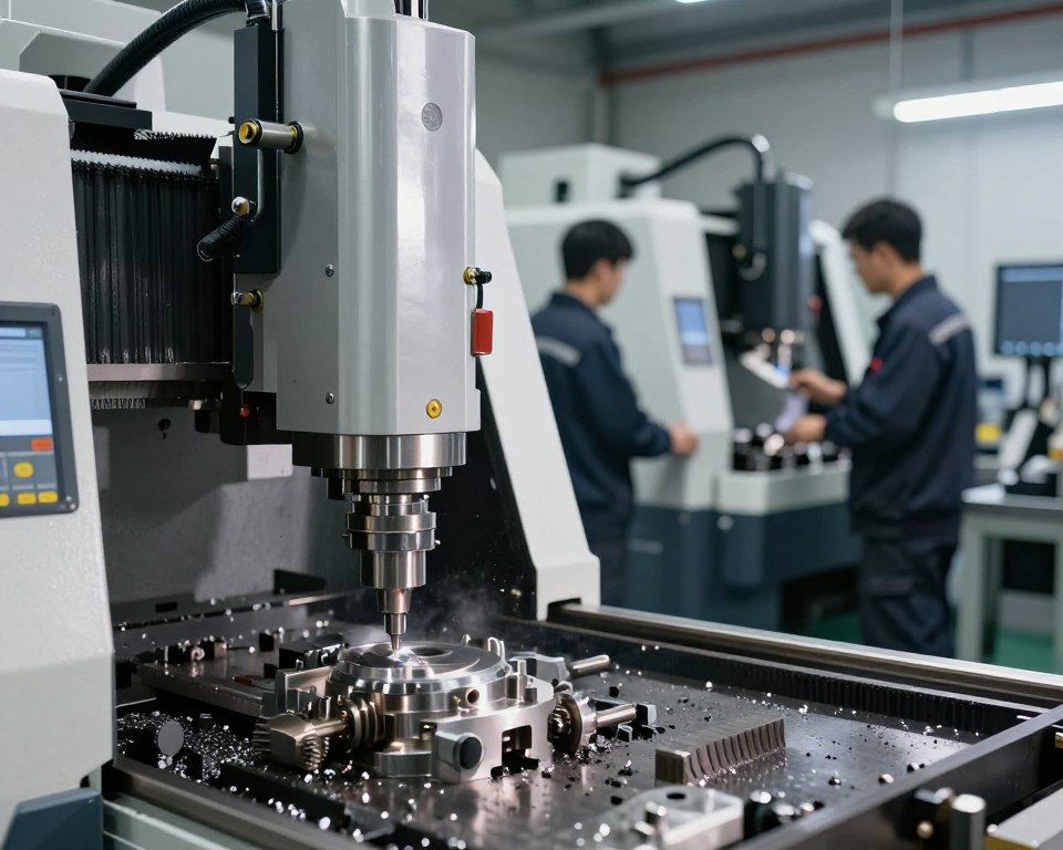
Can a single production path yield metal-grade tolerances, intricate geometry, and thermal-resistant material simultaneously? Welcome to a brief guide on a scalable production tech that renders intricate, high-accuracy ceramic components achievable. This process blends fine powder with a binder to form feedstock. Afterward, that feedstock is molded, cleansed of binder, and sintered until it reaches maximum density.

Read more about injection molds Houston

Key benefits involve freedom of design, reproducibility, precise tolerances, and a surface finish matching metal processes. It works particularly well where machining or tape casting fail at tiny, complex components.

Expect size variation from shrinkage during sintering; upfront design-for-process thinking lowers rework and cost.|Be prepared for dimensional changes due to shrinkage in the sintering phase; strategic design-for-process thinking cut cost and rework. The route supports medium-to-large production batches where tooling and processing speeds warrant the investment.

Applications range from aerospace, automotive, medical devices, electronics, and machinery parts that require wear, thermal, or corrosion resilience.|Sectors include automotive, aerospace, medical devices, electronics, and industrial components requiring resilience to heat, wear, or rust. This article walks the step-by-step process from materials selection through QA and spotlights simulation and metrology tools to ensure reliable outcomes.

Understanding Ceramic Injection Molding And Its Relevance Now

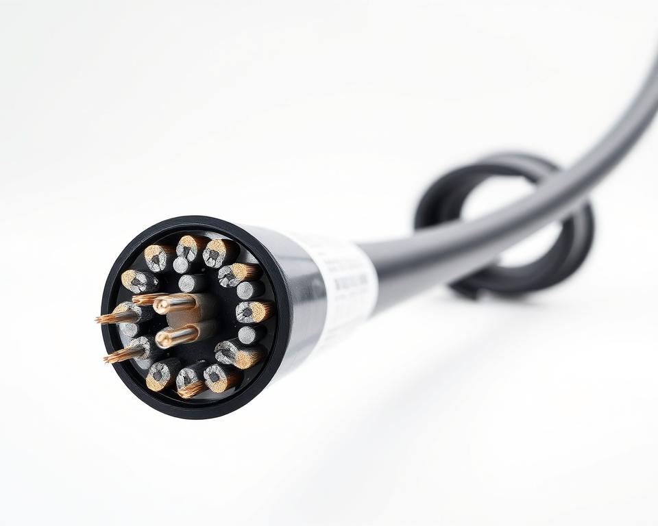
The process of injection molding for micro-powder parts uses a plastic or wax matrix blended with powder to form a moldable feedstock.|Using a wax or thermoplastic binder combined with powder, the injection molding process for fine parts forms a flowable feedstock. That material occupies intricate cavities to produce unfired parts with geometry that are difficult to achieve by casting, compaction, or isostatic pressing.

Comparison With Standard Methods

In contrast to liquid or powder compaction methods, this approach allows for inner passages, overhangs, and thin walls in small-to-mid-sized components.|Unlike powder compaction or slurry methods, this path supports thin walls, undercuts, and voids within small-to-medium items. Throughput is higher and inconsistency is reduced than manual methods.|Output is faster, and deviation is lower compared to manual methods.

Integration Into Modern Manufacturing

Standard workflow: shrinkage design → tooling → injection → binder removal → firing → post-processing.|The usual sequence: design for shrinkage → tooling → molding → debinding → sintering → finishing. Cycle times often vary from seconds to a few minutes per shot.|Shot times typically run from seconds to a couple of minutes. Volume ideal ranges are medium-to-large runs where tooling is amortized.

“Validating designs via DOE trials and test batches reduces uncertainty prior to full production.”

Technique Geometry Throughput Labor
CIM/MIM route Complex (overhangs, channels) Fast Low (automatable)
Casting Moderate Slow High
Isostatic/dry pressing Basic to medium Medium Medium

Downstream, lapping or laser features can refine tolerances after firing.|Downstream, laser features or lapping can improve tolerances. The process integrates well with statistical process control and PPAP protocols, improving traceability and manufacturing control. The distinct advantages today include efficiency, reduced scrap, and the power to unlock designs that were otherwise too costly.

The Core Principles Of Ceramic Injection Molding

This part explains the step-by-step process that converts micro powder and binding agent into a dimensionally stable part ready for sintering.|Here, we break down the step-by-step route converting fine powder and binder into a dimensionally stable part ready for sintering.

Converting Raw Materials To Components

Start by choosing ceramic powder with the correct PSD and surface characteristics.|Start with selecting powder with the right surface area and particle size distribution. These factors dictate packing density, flow, and the final grain structure.

  • Blend powder with a custom binder mix and process into raw material with desired solids loading (typically 55–65 volume percent).
  • Employ injection to create a green part; focus on gating to avoid knit lines and inconsistent density.
  • Remove binder to produce a delicate brown body, subsequently sinter to near-theoretical solidness.

Binders must move for proper filling, maintain geometry while handling, and exit cleanly in binder removal to prevent bubbling or fractures.|Binders must flow to fill well, hold shape during handling, and exit cleanly during debinding to prevent cracks or blisters.

Material rheology — viscosity vs. temperature and shear — governs filling, knit lines, and surface finish.|Feedstock rheology — viscosity against shear and temperature — governs fill behavior, surface finish, and knit lines. CIM machine geometry and screw configuration protect feedstock homogeneity and stop degradation.|Machine geometry and screw/barrel design in CIM protect feedstock homogeneity and prevent degradation.
cast inserts Houston

“Control the processing window: small deviations in heat or pressure frequently lead to short shots, air pockets, or poor surface quality.”

Compared with MIM, this process uses elevated sintering temperatures and different gas environments to suit material chemistry and densification requirements.|Compared to MIM, this route uses different atmospheres and higher sintering temperatures to match densification needs and ceramic chemistry.

Materials And Feedstock Preparation For High Precision Ceramic Parts

Choosing the correct ceramic powders and binders sets the foundation for consistent, accurate components.|The foundation for predictable, high-precision parts is set by selecting the right binders and powders.

Choosing Powders And Key Specs

Aluminum oxide is ideal where wear resistance and electrical insulation are required.|Alumina excels where electrical insulation and wear resistance matter. Zirconia adds toughness for impact-prone parts.|Zirconia adds fracture toughness for parts prone to shock. SiC fits high-temperature and abrasive environments.|Silicon carbide suits abrasive and high-temperature environments.

Manage grain size, morphology, and cleanliness.|Control purity, shape, and particle size. Fine, spherical powder enhances packing and smoothness.|Spherical, fine powder improves surface finish and packing. Non-spherical shapes can increase green strength but might degrade the finished surface.|Irregular particles can boost green strength but may roughen the final surface.

Systems And Ratios Of Binders

Common binder families include paraffins and plastics such as polyethylene and polypropylene, along with additives for complex geometries.|Common binder families include polyolefins such as polypropylene and polyethylene, waxes, plus specialty polymers for difficult shapes. Binder content affects viscosity and removal speed.|Debinding time and melt flow are affected by binder percent.

Mixing And Flow Properties

Compound with a steady sequence: dry mixing, slow polymer addition, followed by controlled temperature and shear.|Compound using a steady sequence: dry powder blending, gradual polymer addition, then controlled shear and temperature. Prevent binder degradation by limiting max heat.|Limit peak temperatures to prevent binder degradation.

Test feedstock with rheometers or mixers to confirm viscosity windows for reliable fill and packing.|Test feedstock using torque rheometers or capillary rheometry to confirm viscosity windows for reliable packing and fill. Aim for powder loading that balances solidness and contraction — usually around 55–65 volume % for dense parts.|Aim for solids loading balancing shrinkage and density — typically around 55–65 vol% for high-density parts.

Drying, Handling, And Storage

Keep materials in airtight containers and follow FIFO.|Store powders in sealed containers and use FIFO. Manage moisture for moisture-sensitive additives and dry feedstock before molding to reduce bubbles and blemishes.|Dry pellets before molding and control humidity for hygroscopic additives to reduce blemishes and voids.

Follow PPE and dust management while handling dust and molten binders.|When handling hot polymers and fine powder, follow dust controls and PPE. Early vendor partnership on material selection speeds validation and reduces iteration risk.|Early supplier collaboration on binder and powder choices lowers iteration risk and speeds validation.

Part Design Guidelines For The Injection Molding Process

Engineering for this route begins with defined objectives: achieve specs and reduce finishing.|Designing for this route starts with clear goals: meet tolerances and limit post-sinter work. Early CAD decisions influence shrinkage, durability, and handling of fragile green components.|Early CAD decisions control shrinkage, strength, and handling of fragile green components.

Managing Wall Thickness, Gates, And Knit Lines

Maintain wall thickness consistent and use gradual transitions to reduce sink and distortion.|Keep wall thickness uniform and use gradual transitions to reduce sink and warpage. Position gates such that material flows from cosmetic or critical areas to prevent knit lines in critical zones.|Place gates so flow moves away from high-stress or cosmetic areas to avoid knit lines in critical zones.

Incorporate a shrinkage factor and resize dimensions in the mold to hit target specs.|Add a shrink map and scale key features in the mold to hit final dimensions. Validate with mold flow analysis and a design review before mold making.|Validate with flow simulation and a DFM review before tooling.

Draft, Radii, And Features For Debinding/Sintering

Provide modest tapers and ample curves to ease demold and lower stress concentrations.|Provide modest draft angles and generous radii to ease demold and lower stress concentrations. Integrate gas vents, sacrificial channels, or setters to accelerate debinding and support delicate geometry.|Integrate vents, sacrificial channels, or setters to speed debinding and support fragile shapes.

Specify datums and inspection points that align with the way components are fixtured during sintering and inspection.|Define datums and inspection points that match how components are fixtured during sintering and QC. Allow slight finishing stock for tight tolerances while avoiding excess that increases expense.|Allow minimal finishing stock for critical fits while avoiding excess that raises cost.

Design Focus Recommendation Benefit Validation
Section thickness Consistent, smooth changes Less warp; predictable shrinkage Simulation / prototype
Gating location Out of cosmetic/stress zones Reduced knit lines Flow sim
Debinding features Vents, channels, setters Intact brown parts; less cracking DFM review

Tooling And Mold Considerations For Ceramic Injection

A well-designed mold set reduces scrap and enhances accuracy over high volume runs.|A well-designed toolset reduces scrap and improves dimensional control across long production runs. Begin by selecting materials and surface engineering to handle abrasive feedstock and close specs.|Start with material choices and surface engineering to handle abrasive feedstock and tight tolerances.

Mold materials must resist abrasion and thermal cycling.|Mold materials should resist abrasion and thermal cycling. Select hardened steels or nickel-based alloys and apply hard coatings for extended tool life.|Select high-performance steels or nickel-based alloys and add wear-resistant coatings for extended tool life.

Optimize texture to assist ejection whilst keeping detail.|Balance surface finish to aid release while preserving detail. Steer clear of textures that trap binder or cause sticking.|Avoid textures that trap binder or cause sticking. Engineer venting to clear gas and volatiles and stop dieseling or short shots.|Engineer venting to clear air and volatiles and prevent burn marks or short shots.

  • Select gate types (edge, submarine, hot tip) and runner layouts to ensure balanced filling and minimize weld lines.
  • Optimize cooling circuits to stabilize cavity temperature and reduce cycle variability.
  • Use robust ejection—plates or air blast—to protect delicate molded parts during ejection.
  • Fit swappable components for fast changes on inlets, vents, and critical dimensions.
  • Account for tolerance stack-ups by adjusting molds for predicted shrink.
  • Embed in-cavity pressure and temperature sensors to track the cycle and enable closed-loop control.
  • Plan service cycles and abrasion inspections to maintain performance stable throughout production.

These measures tighten accuracy and lower downstream rework.|These measures tighten dimensional control and reduce downstream rework. Furthermore, they support scalable production utilizing advanced molding whilst protecting mold assets.|They also support scalable production using modern molding technology while protecting tool investment.

Step-by-Step: Running The Injection Molding Stage

A consistent press cycle depends on thermal profiles, pressure ramps, and operator discipline.|A repeatable press cycle depends on temperature maps, pressure ramps, and operator discipline. Begin with a defined setup list that protects material and machine from heat shock.|Start with a clear start-up checklist that protects feedstock and machine from thermal shock.

Machine Setup: Temperature, Pressure, And Injection Speed

Set barrel and mold temperature profiles to keep flow stable without degrading the polymer.|Set barrel and mold temperature profiles to keep viscosity stable without degrading the binder. Dial in injection speed and packing profiles to fill details while avoiding splaying and flow lines.|Dial in injection speed and pressure ramps to fill complex features while avoiding jetting and flow lines.

Filling, Packing, And Cooling For Tight Tolerances

Employ multi-stage packing to compact green parts and eliminate internal voids.|Use multi-stage packing to densify green parts and reduce internal voids. Balance chill time for ejection strength and speed.|Balance cooling time for handling strength and cycle efficiency. Implement cleaning and material changeover steps to prevent mixing.|Implement purging and material changeover steps to avoid cross-contamination.

Safe Demolding Of Green Parts

Use slick coatings and measured mold release where needed.|Apply low-friction coatings and measured mold release where needed. Use gentle ejection and soft handling for delicate features.|Use controlled ejection and guarded fixtures for delicate features. Instruct techs to identify flaws early and halt the production if needed.|Train operators to spot defects early and stop the run if needed.

Control Target Outcome
Barrel / mold temp Stable viscosity window Fewer short shots; consistent surface
Injection profiles Staged profiles Complete fill; reduced weld lines
Hold & Cool Multi-stage; balanced time Uniform density; dimensional stability

Debinding Methods And Best Practices

Effective debinding is a critical step that turns a fragile green part into a furnace-ready item.|Effective binder removal is a critical step that turns a fragile green part into a sinter-ready component.

Two main removal techniques are common: chemical debinding and heat debinding.|Two main debinding methods are common: solvent debinding and thermal debinding. Chemical removal removes the soluble binder fraction first.|Solvent debinding extracts the soluble binder fraction first. Thermal debinding then burns off the remaining binder by controlled heating.|Thermal debinding then removes the remaining polymer by controlled pyrolysis.

Comparing Solvent And Thermal Techniques

Solvent debinding is fast for soluble phases and lowers gas pressure during the next stage.|Solvent debinding is fast for soluble phases and reduces internal pressure during the next stage. Thermal debinding is slower but necessary to remove resistant plastic.|Thermal debinding is slower but needed to remove hard-to-dissolve polymer. Selecting the correct method depends on binder type and part geometry.|Choosing the right method depends on binder chemistry and part geometry.

Preventing Defects In Debinding

Fixture choice and positioning are crucial.|Fixture choice and part orientation matter. Support fragile areas and permit open channels for volatiles to prevent fractures and distortion.|Support fragile areas and allow free escape paths for volatiles to prevent cracking and distortion.

Use slow heat-up rates, staged hold times, and controlled airflow to avoid pressure spikes that lead to defects.|Use gentle heating ramps, staged hold times, and controlled airflow to avoid pressure spikes that cause blistering. Thick sections and deep pockets need extended times or local vents.|Thick sections and blind holes need longer cycles or local vents.

Select chemicals with recovery systems and proper ventilation.|Pick solvents with recovery systems and proper ventilation. Follow safety sheets and local environmental rules to safeguard staff and comply with regulations.|Follow MSDS guidance and local environmental rules to protect workers and comply with regulations.

  • Test samples and test pieces to confirm complete debinding prior to sintering.
  • Look for odor, color change, or unexpected mass loss profiles—these indicate leftover binder.
  • Troubleshoot skinning, layer separation, or slump by reducing heat rates, venting better, or adjusting fixture layout.

Debinding success depends on molding and injection quality; voids or knit lines often become cracks during debinding.|Debinding success ties back to molding and injection quality; voids or knit lines often become failure points during removal. Record debinding curves and weight data to standardize production and ensure quality.|Record debinding curves and mass loss data to standardize processing and protect final part quality.

Sintering To Final Density And Performance

Controlled sintering is the process that converts a weak brown part into a dense, service-ready component.|Controlled sintering is the step that converts a fragile brown shape into a dense, service-ready part. The furnace cycle sets microstructure, porosity, and mechanical properties that determine long-term performance.

Atmospheres, Shrinkage Control, And Temp Profiles

Implement a three-stage profile: gentle heating to burn off leftover binder, a controlled ramp to the sintering zone, and a controlled cooling to avoid cracking.|Use a three-stage profile: slow heat-up to remove residual binder, a controlled ramp into the densification range, and a measured cool-down to avoid thermal shock.

Align atmosphere to chemistry: oxygen for oxides, inert or hydrogen for carbides and certain engineered mixes.|Match atmosphere to material: air for alumina-type oxides, inert or reducing for carbides and some engineered mixes. The right gas preserves chemistry and color while limiting grain boundary reactions.

Track shrinkage with test bars and incorporate those values into mold scaling.|Measure shrinkage with sacrificial coupons and incorporate those values into cavity compensation. Create trays and supports to prevent distortion and permit airflow.|Design setters and supports to restrain warpage and allow uniform gas flow.

Optimizing For Strength, Wear, And Corrosion

Firing changes crystal size and voids, which control bending strength and toughness.|Sintering alters grain size and porosity, which drive flexural strength and fracture toughness. Target high density with minimal grain coarsening to achieve specs.|Aim for high density with minimal grain coarsening to meet mechanical targets.

Choose material chemistry and dwell times to optimize corrosion resistance and hardness for wear resistance.|Select material chemistry and sinter soak times to optimize corrosion resistance and surface hardness for wear resistance. Evaluate post-sinter HIP where micro-pores affects life or hermeticity.|Consider post-sinter HIP where residual porosity affects fatigue or sealing.

  • Record profiles and utilize thermocouples or pyrometry to validate heat accuracy.
  • Control loading and spacing to guarantee even temperature and gas flow.
  • Watch for defects: sagging, exaggerated grain growth, and voids—slow ramps and fixtures frequently fix these.
Parameter Setting Effect Tip
Ramp rate 1–5 °C/min (debind) / 5–20 °C/min (sinter) Reduces cracking; controls grain growth Align with mass/binder
Dwell settings Material-specific peak; minutes–hours Density increase; porosity closure Use samples to verify
Gas environment Air / inert / reducing Maintains chemistry; stops oxidation Flow meters and gas purity checks
Post-sinter options HIP/Annealing Eliminate residual porosity; boost strength Apply when parts need max performance

“Consistent firing cycles and validated furnaces directly increase yield and cut finishing rework.”

Quality Control, Metrology, And Tolerances

A strong metrology plan converts variability in shrinkage into predictable tolerances.|A robust metrology plan turns uncertainty in shrinkage into predictable tolerances. Begin with defined checkpoints at all stages to detect errors early.|Start with clear inspection gates at green, brown, and sintered states to catch deviations early.

Compensating For Shrinkage In The Mold

Use shrinkage correlation charts from pilot runs to scale mold sizes.|Use shrinkage correlation charts from pilot runs to scale cavity dimensions. Confirm with sacrificial coupons and update the tooling offsets before full tooling runs.|Validate with sacrificial coupons and update the mold compensation map before full tooling runs.

Surface Quality, Microstructure, And Porosity Checks

Check surface finish and density using profilometers and Archimedes testing.|Inspect surface finish and density using profilometers and Archimedes testing. Micro-CT and optical scans show voids that affect mechanical properties.|Micro-CT and optical scans reveal internal pores that affect mechanical properties.

  • Define QC plans across all phases with pass/fail gates.
  • Use metrology: CMM, optical scanners, profilometers, micro-CT for internal verification.
  • Correlate grain size and pore distribution with durability and wear performance.
Checkpoint Tool Measurement Action
Green parts Optical scan Dimensional conformity Adjust mold compensation
Brown parts Micro-CT Void distribution Modify debind cycle
Sintered parts CMM / Surface check Specs / Roughness Finalize process & release
Lot control SPC software Capability / Density Hold or release lots

Implement statistical control and capability studies prior to approval.|Implement SPC and capability studies before PPAP. Keep records from lot-level raw materials to batches.|Maintain traceability from lot-level powders and binders through batches. Check tools, run MSA, and set reject procedures with root-cause action plans.|Calibrate gauges, run MSA, and define nonconformance flows with root-cause action plans.

“Reliable data and records complete the circle on production quality.”

Applications In The US Market

Domestic producers prefer CIM when parts need to combine low mass and durability.|Domestic producers favor feedstock-based production when parts must combine low mass and high wear resistance. In aerospace, automotive, healthcare, and electronics, vendors use this route to hit tight specs and extreme conditions.|Across aerospace, automotive, medical, and electronics, suppliers use this route to meet tight specs and harsh environments.

High Strength-To-Weight Components In Aerospace

For aviation, engineers select lightweight bearings, nozzle inserts, and thermal barrier parts that demand efficiency.|In aerospace, manufacturers specify lightweight wear components, nozzle inserts, and thermal barrier parts that demand high strength-to-weight performance.

These parts boost fuel efficiency and withstand thermal shock and shaking in engines and actuation systems.|These components improve fuel efficiency and survive temperature cycling and vibration in engines and actuation systems.

Automotive: Thermal Stability And Durability

Car applications include impellers, sensor housings, and exhaust parts that require thermal stability and longevity.|Automotive use cases include pump components, sensor housings, and exhaust-related insulators that need thermal stability and long-term durability.

Replacing steel parts for engineered powdered parts stops rust and prolongs service life in harsh engine bays.|Swapping metal parts for engineered powdered parts reduces corrosion and extends service life in harsh under-hood environments.

Medical/Electronics: Small, Precise Parts

Medical and tech markets benefit from tiny insulators, ferrules, implants, and safe wear parts.|Medical and electronics markets benefit from micro-scale insulators, ferrules, implantable device components, and biocompatible wear parts.

These components require precision, insulation, and validated biocompatibility or electrical testing prior to launch.|These components require tight tolerances, dielectric performance, and validated biocompatibility or dielectric testing prior to production release.

  • Performance advantage: excellent wear resistance and chemical resistance render these components perfect for harsh service.
  • Certified manufacturing often follows AS9100, auto standards, or medical standards with detailed documentation and tracking.
  • DFA matters for hybrid systems that join these parts to metals or plastics.
Stage Typical U.S. Lead Time Note
Tooling to pilot 1.5 – 3 months Varies by complexity
Sample to Production 4–8 weeks Validation and qual testing
Total 2.5 – 5 months Domestic supply chains shorten logistics

Validation steps involve biocompatibility studies for implants and dielectric testing for devices.|Validation steps include biocompatibility studies for implants and dielectric testing for electronics. Many success stories demonstrate this approach replacing metal designs to save weight and remove corrosion failure modes in service.|Many success stories show this approach replacing metal designs to cut weight and remove corrosion failure modes in service.

Costs, Cycle Times, And When CIM Beats Machining

Understanding economics helps determining whether formed-powder production or machining is the smarter path.|Understanding economics helps decide whether formed-powder production or machining is the smarter path. Begin by listing the main cost drivers and how speed affects cash flow.|Start by mapping the main cost drivers and how cycle time affects cash flow.

Primary Cost Factors

Tooling and mold depreciation frequently dominate upfront cost.|Tooling and mold amortization often dominate initial spend. Hardened tools or interchangeable inserts raise up-front cost but reduce unit cost at scale.|High-performance steels or interchangeable inserts raise up-front cost but lower per-piece cost over volume.

Material/feedstock, press time, sintering time, manpower, and scrap contribute to true landed cost.|Material/feedstock, press time, furnace soak, labor, and yield losses all add to true landed cost. Post-processing, QA, and shipping prep also matter.|Secondary finishing, inspection, and packaging also matter.

Factor Impact How to reduce
Tooling / mold High CapEx; low OpEx Modular inserts; amortize over volume
Materials Variable cost; impact on yield Bulk buy; optimize mix
Machine & furnace time Sets throughput and cash flow Match molding to sintering
Scrap rate Profit killer Design for uniform walls and gate locations

CIM Advantages Over Machining

In complex shapes and mid-to-high volumes, per-part costs fall below machining.|For complex geometry and mid-to-high volumes, per-part costs fall below machining. Cutting hard ceramics creates much scrap and slow times for inner features.|Machining brittle blanks creates much scrap and long cycle times for internal channels.

CNC still wins for very low volumes, large parts, or when specs need tight post-sinter finishing.|Machining still wins for very low volumes, oversized pieces, or when tolerances need tight post-sinter finishing.

“Smart design and scheduling convert overhead into low unit prices.”

Quoting Rules Of Thumb

  • Calculate tooling payback: mold cost ÷ expected units = tool cost per unit.
  • Add material, machine time, furnace pro rata, work, QA, and packaging to get unit cost.
  • Include a scrap buffer (5–15%) and a finishing cost.

This method outlines total cost of ownership and show where design, process choices, and better molds yield the greatest benefits.|These steps frame total cost of ownership and show where design, process choices, and smarter tooling deliver the biggest advantages.

Solving Common CIM Defects

Finding the root cause of mis-fills or distortion needs both metrics and logic.|Finding the real cause of short shots or warpage needs both data and structured problem-solving. Follow a simple checklist to distinguish problems that start in injection, binder removal, or sintering.|Use a simple checklist to separate problems that start in molding, debinding, or sintering.

Diagnosing Typical Defects

Short shots and voids occur if fill speed or pressure is too low, air vents are clogged, or material contains moisture.|Short shots and voids happen when injection speed or pressure is too low, vents are blocked, or feedstock carries moisture.

Warpage frequently comes from unequal packing, uneven cooling, or bad fixturing during the furnace.|Warpage often traces to unequal packing, nonuniform cooling, or poor support during sintering.

Delamination and weak knit lines are fixed by new gates, higher melt temps, or balanced flow across cavities.|Delamination and weak knit lines respond to gate redesign, higher melt temps, or flow balancing across cavities.

  • Debinding blistering/cracks: slow heating, thick walls, or poor solvent penetration.
  • Inspect mold wear and scratches when defects appear following long runs.
  • Implement incoming inspection to control feedstock variability and moisture.

“Use structured root-cause tools such as Ishikawa and the Five Whys to isolate stage-specific failures.”

Issue Root Cause Fix
Short shot/void Low parameters, clogged vents Increase injection pressure; clear vents
Warp Uneven packing/cooling Fix fill; change cooling
Blister/crack Debind profile issues Slower heat; check solvent

Perform DOE to tune parameters and verify solutions.|Run DOE to tune parameters and verify fixes. Monitor failure codes and Pareto charts to target actions.|Track defect codes and Pareto charts to focus improvements. Close the loop among molders, furnace techs, and QA to shorten time-to-correct and improve overall quality in the plant.|Close the loop between press operators, furnace techs, and QA to shorten time-to-correct and raise overall quality in the process.

Compliance, Sustainability, And Safety

Safeguarding workers and the planet is just as critical as meeting specs in modern powder-based production.|Protecting workers and the environment is as important as hitting tolerances in modern powder-based production.

Safety With Powders And Binders

Use gear: masks, chemical-resistant gloves, glasses, and protective clothing for powder and hot binder work.|Use PPE: N95 or P100 respirators, chemical-resistant gloves, eye protection, and protective clothing for dry powder and hot binder work.

Use local exhaust ventilation and filters to control airborne powder.|Install local exhaust ventilation and HEPA filtration to control fugitive dust. Cover transfer points and use grounding to mitigate sparks.|Enclose transfer points and use grounded transfer lines to reduce static risks.

“Educate staff on cleanup, chemical safety, and storage rules—regular drills ease audits.”

Considerations For Waste, Energy, And Recycling

Segregate waste streams: loose powder, binder waste, chemicals, and general refuse.|Segregate waste streams: loose powder, used binder, solvent residues, and general refuse. Mark containers and keep streams apart for recovery.|Label containers and keep solvent and powder streams separate for recovery.

Adopt solvent recycling and regrinding where quality permits.|Adopt closed-loop solvent recovery and controlled feedstock regrind where quality permits. Doing so reduces disposal costs and saves raw materials.|This reduces disposal costs and preserves raw materials.

Schedule furnace loads to fill the kiln and reduce energy spikes.|Schedule furnace loads to maximize fill and minimize peak demand. Improve insulation, use high-efficiency motors and VFDs, and log energy data for ISO 14001-style efficiency.|Improve insulation, use high-efficiency motors and variable-speed drives, and log energy data for ISO 14001-style continuous improvement.

Comply with safety and environmental regulations for hazardous air pollutants, VOCs, and recordkeeping.|Follow OSHA and EPA rules for hazardous air pollutants, solvent emissions, and recordkeeping. Keep SOPs, logs, and MSDS available for audits.|Keep documented procedures, training records, and material safety data sheets ready for audits.

Engineer parts to reduce weight and processing time—these actions lower power and provide distinct green benefits whilst maintaining production steady.|Design parts to cut mass and cycle time—these simple choices lower energy use and offer clear environmental advantages while keeping production reliable.

Next Steps: Bringing Your Ceramic Injection Molding Project To Production

Convert design intent to proven manufacturing by sequencing tests, mold trials, and pilot runs.|Turn design intent into reliable production by sequencing material trials, tool proofs, and pilot runs.

Checklist: pick feedstock, run a DFM review, run simulation, build a prototype mold, complete validation runs, then execute approval or equivalent.|Practical checklist: pick feedstock, run a DFM review, simulate flow, build a prototype mold, complete validation runs, then execute PPAP or equivalent.

Establish goals from Quote → proto mold → capability studies → FAI → SOP.|Set milestones from RFQ → prototype tool → capability studies → first article inspection → SOP. Agree deliverables and schedules with suppliers to de-risk decisions.|Agree deliverables and timelines with suppliers to de-risk early choices.

Document quality plans, work instructions, and quality metrics prior to pilot production.|Document control plans, work instructions, and quality metrics before pilot production. Plan capacity for machines, furnace volume, debinding, and staffing.|Plan capacity for press tonnage, furnace volume, debind throughput, and staffing.

Aim for early wins where accuracy and complexity create value.|Target early wins where precision and complex geometry add value. Maintain consistency with preventive maintenance, calibration, and audits.|Maintain quality with preventive maintenance, gauge R&R, and periodic requalification.

Ready to proceed? Ask for a review and a cost model using your designs, volumes, and performance needs.|Ready to proceed? Request a feasibility review and a cost model based on your parts, volumes, and performance needs.

Frequently Asked Questions

itemprop=”name”>What is the process behind making precision ceramic parts with injection techniques?

The process begins with blending ceramic or carbide powder with a polymer-based binder to form a uniform material.|The process starts by mixing fine oxide or carbide powder with a polymer-based binder to form a homogenous feedstock. The mixture is shot into a mold under pressure to create a green part.|That feedstock is shot into a mold under pressure to create a green part. After molding, the polymer is extracted via debinding, and the part is sintered to reach final density and strength.|After molding, the binder is removed through solvent or thermal debinding, and the part is sintered to reach final density and mechanical properties. Each stage — mixing, molding, washing, and sintering — requires control to hit tight tolerances and quality goals.|Each stage — compounding, molding, debinding, and sintering — must be controlled to meet tight tolerances and material performance targets.

itemprop=”name”>What is the difference between CIM and slip casting or pressing?

In contrast to pressing or casting, that form items one at a time or require finishing, CIM enables high-volume production of complex geometries with details and consistent repeatability.|Unlike pressing or slip casting, which shape parts one at a time or require significant machining, injection enables high-volume production of complex geometries with fine features and consistent repeatability. It also lowers grinding for most components, increasing yield and lowering per-part cost in volume.|It also reduces post-sintering machining for many components, improving material yield and lowering per-part cost at scale.

itemprop=”name”>What materials are used in ceramic injection molding?

Common powders are aluminum oxide, zirconium oxide, and silicon carbide.|Common powders include alumina, zirconia, and silicon carbide. Carbides appear when extreme wear resistance matters.|Tungsten carbide blends appear where extreme wear resistance matters. Powder selection depends on strength needs, heat resistance, corrosion resistance, and electrical properties.|Powder selection depends on required strength, thermal stability, corrosion resistance, and electrical properties. Correct chemistry and particle size distribution also affect feedstock flow and sintered density.|Proper powder surface chemistry and particle size distribution also affect feedstock flow and final density.

itemprop=”name”>Function and selection of binders in CIM?

Binding agents provide strength and lubricity in the mold, then must be removable avoiding damaging the part.|Binders provide cohesion and flow during molding, then must be removable without harming the part. Typical systems employ waxes and plastics in set amounts to manage flow, green strength, and removal.|Typical systems use waxes and polymers in controlled ratios to balance viscosity, green strength, and debinding behavior. Selection depends on part geometry, removal process, and environmental or safety requirements.|Selection depends on part geometry, debinding method, and environmental or safety requirements.

itemprop=”name”>Design strategies for shrinkage and tolerances?

Designers compensate by sizing mold cavities to offset expected linear shrinkage in the furnace.|Designers compensate by scaling mold cavities to offset predictable linear shrinkage during sintering. They also control walls, fillets, and locate gates to minimize welds and warping.|They also control wall thicknesses, add radii, and locate gates to minimize knit lines and deformation. Working closely with the molder aids in set achievable tolerances using material and process capability.|Close collaboration with the manufacturer helps set achievable tolerances based on material and process capability.

itemprop=”name”>What mold considerations affect part quality?

Mold material, polish, air vents, and gate and runner design affect filling, packing, and ejection.|Mold material, surface finish, venting, and gate and runner design all influence filling, packing, and demolding. Hardened steels with smooth surfaces lower surface defects.|Hardened steels with polished cavities reduce surface defects. Proper venting prevents air pockets and mis-runs, while good gates yield consistent feedstock flow and limit knit lines.|Proper venting prevents trapped gas and short shots, while optimized gates yield consistent feedstock flow and reduce weld lines.

itemprop=”name”>Optimizing molding for precision dimensions?

Settings — barrel and mold temperature, injection speed, and holding pressure — are tuned to ensure complete cavity fill and consistent packing.|Machine parameters — barrel and mold temperature, injection speed, and holding pressure — are tuned to ensure complete cavity fill and consistent packing. Chill time and demolding timing are fixed to avoid warping of green parts while keeping cycle efficiency.|Cooling and demolding timing are set to avoid distortion of green parts while maintaining cycle efficiency. Monitoring metrics assists to keep variation low.|Monitoring process data helps keep variation low.

itemprop=”name”>When to use solvent vs thermal debinding?

Solvent debinding dissolves soluble binder fractions and is gentle for complex features.|Solvent debinding extracts soluble binder fractions and is gentle for complex features. Thermal debinding ramps temperature to evaporate or pyrolyze the remainder and is often applied after solvent steps.|Thermal debinding ramps temperature to evaporate or pyrolyze the remainder and is often used after solvent steps. The decision relies on binder type, wall size, and risk of defects.|The choice depends on binder chemistry, part thickness, and risk of cracking or blistering.

itemprop=”name”>Avoiding cracks and blisters during debinding?

Manufacturers regulate heating rates, verify venting paths, and use staged solvent/thermal sequences matched to material.|They control heating rates, ensure venting paths, and use staged solvent/thermal sequences tailored to feedstock. Uniform binder removal and reducing gas build-up during burnout reduce forces that cause cracks or blisters.|Uniform binder removal and minimizing internal pressure during decomposition reduce stresses that cause cracks or blisters.

itemprop=”name”>What sintering practices ensure final strength and wear or corrosion resistance?

Furnace cycles — temperature, hold time, ramps, and gas — are optimized for shrinkage while controlling coarsening.|Sintering profiles — temperature, hold time, ramp rates, and atmosphere — are optimized for densification while limiting grain growth. Specific gases or HIP may be used to achieve full density, toughness, and surface properties such as durability.|Controlled atmospheres or isostatic post-sinter densification may be used to achieve target density, strength, and surface properties like wear and corrosion resistance.

itemprop=”name”>QC methods for CIM production?

QC employs dimensional inspection corrected for shrink, grain analysis, porosity checks, and mechanical testing.|Quality control uses dimensional inspection adjusted for shrinkage, microstructure analysis, porosity checks, and mechanical testing. SPC tracks key parameters to keep consistency, and first-article inspection confirms tooling compensation and results.|Statistical process control monitors key parameters to maintain repeatability, and first-article inspection validates tooling compensation and sintering outcomes.

itemprop=”name”>Which industries in the United States most benefit from this manufacturing route?

Aerospace, auto, medical devices, and electronics are key users.|Aerospace, automotive, medical devices, and electronics benefit most. Typical uses are wear parts, strong parts requiring precision, and miniature parts when machining would be too expensive.|Typical uses include thermal or wear-resistant components, high-strength parts requiring tight geometries, and miniature parts where machining would be impractical or costly.

itemprop=”name”>CIM vs Machining: When is CIM cheaper?

It pays off as volumes rise, shapes are intricate, or combining parts reduces assembly.|It becomes economical when volumes rise, geometries are complex, or part consolidation reduces assembly steps. High tooling cost is amortized over many parts, and the reduced need for cutting lowers scrap and unit cost.|High tooling cost is amortized over many parts, and the reduced need for machining lowers material waste and cycle cost per component.

itemprop=”name”>Diagnosing common CIM molding defects?

Incomplete parts, holes, warpage, and peeling are caused by material issues, poor mold venting, wrong settings, or bad processing.|Short shots, voids, warpage, and delamination can stem from feedstock problems, poor mold venting, incorrect process settings, or improper debinding/sintering. Troubleshooting links flaws to stage, then checks factors like force, temperature, or flow for correction.|Root-cause analysis maps defect location to process step, then isolates variables like pressure, temperature, or feedstock rheology for correction.

itemprop=”name”>Safety and environment in CIM processing?

Use ventilation, dust controls, and gear while handling particulates.|Use local exhaust ventilation, dust controls, and appropriate PPE when handling fine powders. Dispose of solvent and binder waste per regulations.|Manage solvent and binder waste per OSHA and EPA guidelines. Regrinding and efficient firing lower environmental footprint.|Recycling of scrap feedstock and energy-efficient sintering reduce environmental footprint.

itemprop=”name”>Moving from prototype to production in CIM?

Start with choosing materials and a DFM review.|Start with material selection and a design review for manufacturability. Run samples to validate material, tooling, and thermal profiles.|Produce pilot parts to validate feedstock, mold compensation, and thermal profiles. Refine tooling and process parameters, then grow with qualified suppliers who can show consistent metrology and control.|Iterate tooling and process parameters, then scale with qualified suppliers who can demonstrate consistent metrology and process control.

Categories
Manufacturing

The Evolution of AMT Endoscopy Systems

AMT’s Endoscopy in Singapore: A Complete Guide.

“Do not stop questioning.” — Albert Einstein.

AMT’s endoscopy combines precise manufacturing with patient care. We will explore how AMT connects making devices to supporting gastrointestinal procedures in Singapore.

Accuron Technologies recently made a big move with https://amt-mat.com/business/mim/. They placed Aurum Healthcare under Advanced Materials Technologies. They also added sterilization and cleanroom capabilities in Johor Bahru, strengthening AMT’s presence in Tuas and Dongguan. With this integration, AMT is able to manage a full chain from components to cleanroom assembly.

You’ll learn why AMT’s endoscopy services are important for healthcare providers, device makers, and patients. Topics include manufacturing technologies and cleanroom services. We discuss partnerships, clinical use cases, safety rules, the costs, training for the workforce, and new trends like AI, robotics, and minimization.

Singapore enables medical tourism in the region, which makes AMT’s endoscopy services central for Southeast Asia. Up next, we’ll look into the manufacturing advances and clinical uses that keep modern medical endoscopy both effective and able to grow.

AMT’s Role in Singapore’s Endoscopy & Medtech Manufacturing

Advanced Materials Technologies (AMT) is a key player in Singapore for making precision metal parts. They specialize in metal injection moulding and additive metal manufacturing. AMT supplies components for urology, endoscopy, and robotic surgery and serves the needs of global brands seeking top-notch components.

Company background and strategy

Accuron Medtech was created to boost growth in the Asia-Pacific medtech scene, sharpening AMT on medical devices. Its teams specialize in design-for-manufacturing across additive and MIM processes needed for top-tier endoscopy products.

Scale Through Targeted Additions

The purchase of Aurum made AMT’s services even better by adding validated cleaning and assembly. Aurum Healthcare’s Johor Bahru facility increased AMT’s capacity and scope, allowing coverage from metal parts to sterilization and plastic assembly.

AMT - endoscopy

Partnering with OEMs and Robotics

AMT supports endoscopy device makers with precise parts and cleanroom assembly. They manage everything from DFM to ensuring sterility, speeding up launches while strengthening quality and cost control.

By integrating component production with sterilization and assembly, AMT is a strong partner for endoscopic and surgical robotics OEMs, streamlining programs, speeding validation, and readying advanced tools for surgery.

Scope & Significance of AMT’s Endoscopy

Here we outline AMT’s role in healthcare and device making. “AMT’s endoscopy” refers to the parts and services AMT provides for endoscopic procedures—from precise metal components to cleanroom-assembled and sterilized tools used in clinical settings.

Definition Across Manufacturing & Clinical Use

AMT manufactures high-accuracy metal parts via MIM and 3D printing, and handles cleanroom assembly, sterilization, and tracking for clinical use. These sterile, validated parts are essential for safe endoscopy.

Manufacturing versus clinical endoscopy services

AMT handles engineering, quality control, regulation, and production—but does not clinical care. Hospitals and clinics conduct procedures using AMT’s parts, maintaining a clear division of responsibilities.

Why Singapore’s cluster matters for regional healthcare and medical tourism

Singapore combines advanced manufacturing, strict regulation, and top clinical centers, helping OEMs quickly move designs to market. Local supply and services make Singapore an important location for medical endoscopy and attract regional patients.

  • Quicker prototyping and supply for hospitals and center networks
  • Strong quality controls meeting export and local clinical requirements
  • Closer manufacturer-clinician collaboration to refine instruments

Understanding the line between AMT’s manufacturing and hospital services demonstrates how the ecosystem drives better care, aiding doctors and enabling device companies to expand innovation.

Advanced endoscopy technology produced and supported by AMT

AMT produces key components for advanced endoscopy used in Singapore and by regional OEMs, blending conventional metal forming with modern processes to meet high standards.

Metal injection moulding and additive metal printing

AMT specializes in small, strong parts—linkages, tips, housings—via MIM, and uses 3D printing for complex shapes unsuitable for subtractive methods, enhancing assembly and delivering reliability.

Sterilization, Clean Assembly & QA

AMT provides audited sterilisation and clean assembly with ISO-aligned systems, including trackability for consumables and plastics, supporting catheter and disposable needs while remaining compliant.

Smaller Parts, Higher Imaging Demands

As parts shrink, e.g., camera housings, AMT meets precision demands where imaging and therapy converge—providing tiny, durable components suited to modern scopes.

Benefits include fewer parts, consistent performance, and easier sterilisation checks—accelerating development and enabling improved diagnosis and therapy.

Types of gastrointestinal endoscopy and procedures linked to AMT products

GI endoscopy ranges from diagnostic checks to complex interventions. Device makers need tough, exact metal components and re-sterilizable tools—AMT supplies both manufacturing and sterile assembly to Singapore hospitals.

Diagnostics and Video Endoscopy

Diagnostic scopes use imaging and biopsy features; video endoscopy needs rigid, robust housings. AMT provides tip components and biopsy forceps parts, keeping image stability and device reliability.

Biopsy tools are sterilized and tracked; reliable components cut downtime and enable AI-assisted workflows.

Therapeutic procedures: polypectomy, hemostasis, EMR

Therapeutic devices—snares, cutters—need heat- and stress-resistant precision. AMT’s fabrication delivers precise snare wires and cutters, with sterile lines preparing them OR-ready.

Interventional and hybrid procedures enabled by advanced components

Hybrid approaches combine endoscopy with other techniques, demanding specialized components. AMT enables navigation and robotic integrations via dependable designs and strict sterile processes.

  • Tip assemblies for video and gastro scopes
  • High-precision snare wires and cutting tools for therapy
  • Articulated linkages and connectors for interventional surgery

Clinical Benefits of Minimally Invasive Endoscopy

Minimally invasive endoscopy improves patient care in Singapore—faster recovery and lower risks. With tiny tools and advanced optics, doctors operate through small access points, reducing hospital time.

AMT specializes in precise parts and sterile items clinicians rely on for routine care.

Reduced sedation, faster recovery and patient comfort

Lower sedation is safer for the elderly and comorbid patients, allowing quicker discharge. Ergonomic devices and miniaturized parts make procedures gentler, boosting acceptance.

Single-Visit Diagnosis and Therapy

Modern scopes enable diagnosis and therapy in a single visit, reducing risk and cost while improving convenience.

HD Imaging + AI for Accuracy

High-definition imaging reveals finer details; AI adds real-time analysis. Well-engineered optics and mechanics support early detection and better planning.

  • Stable, sharp imaging supports AI detection
  • Advanced manufacturing keeps optics aligned and protected
  • Validated sterile workflows lower infection risk

Endoscopy specialist workforce and training in Singapore’s AMT ecosystem

Singapore’s endoscopy teams blend clinical expertise and technical skill, supported by hospitals, national programs, and industry partners to sustain high quality.

Competencies for Complex Cases

Advanced techniques require precision and device fluency—mucosal resection, polypectomy, hemostasis—plus cross-disciplinary learning with robotics and AI. Simulators and structured assessments transfer knowledge safely; device literacy reduces risk.

How Providers and OEMs Upskill Teams

Major hospitals offer specialized training and continuing education. Manufacturers deliver device operation, care, and maintenance training for practical understanding.

Blending courses with SG’s initiatives and OEM input builds a well-rounded learning path.

Concentration of expertise and access

Expertise concentrates in large centers, boosting complex case outcomes and training, but limiting smaller sites. Regional patients travel to Singapore for specialized care, highlighting its hub role.

Outreach, tele-mentoring, and expanded training help distribute excellence and reduce gaps.

Endoscopy center infrastructure and patient pathway in Singapore

At Singapore endoscopy centers, the journey runs from referral to recovery with defined steps, including minimal-sedation or awake options.

What patients can expect: referral, assessment, consent

Pre-procedure checks assess history, medications, bleeding risks, and fasting. Teams walk through benefits and risks with plain consent forms; many sites offer same-day pathways to cut waiting.

Theatre standards, sterilisation workflows and cleanroom impacts

Clean theatres and documented instrument flows are critical. Unified sterilization, assembly, and device supply improve safety and simplify tracking of single-use items.

Documented workflows reduce infection risk and ensure standards are met; working with one provider can speed supply and simplify chains.

Aftercare, Follow-Up & Health Records

Post-procedure care centers on recovery, complication watch, and results communication. Linking with national records enables follow-ups and device traceability from maker to patient.

Regulation, QA & Device Safety

In Singapore, endoscopy devices adhere to high standards. The Health Sciences Authority checks registration, documentation, and ongoing safety before clinic use.

Singapore regulatory landscape for medtech

Hospitals and suppliers demonstrate HSA compliance via risk management, clinical evidence, and quality checks. Global standards are referenced approvals for proven devices.

ISO, Sterility Validation & Traceability

Quality systems follow ISO frameworks. Sterilisation uses validated methods to guarantee sterility. AMT’s traceability follows each device from build to use for rapid responses if needed.

Governance & Surveillance

Hospitals track performance and report issues via registries. AMT’s documentation aids clinicians and OEMs in addressing problems; oversight expands with smarter devices to cover data and responsibilities.

Paying for Advanced Endoscopy

Advanced endoscopy is costly for providers and patients—high-end scopes and robotics have large capital costs plus service contracts.

Costs rise with complex imaging and AI requirements. Where makers also manage sterilization and parts, hospitals may save via streamlined supply.

Training and dedicated spaces remain costly, affecting affordability. Large centers absorb costs better than smaller sites, influencing access.

Medical tourism brings revenue yet may shift focus toward premium services, raising equity questions.

Leaders explore group purchasing and partnerships to balance fairness with innovation.

What’s Next in Endoscopy

Rapid advances reshape clinician-manufacturer collaboration in Singapore and the region. AMT’s supply chain links precision manufacturing with clinical needs for performance and safety.

AI-Driven Detection helps spot subtle lesions, relying on stable feeds and consistent equipment so algorithms flag issues as they happen.

Regulatory and ethical issues accompany AI adoption—testing for fairness, data handling, accountability, and consent are addressed across makers and providers.

Navigation and tool integration update surgical precision via overlays, articulation, and robotics, where OEM-manufacturer coordination meets high thresholds.

  • Robots enhance reach and steadiness
  • Navigation tightens targeting
  • Combining modalities reduces re-interventions

Going Smaller lead to tiny cameras and instruments that demand advanced metalwork and careful assembly able to withstand reprocessing while maintaining clear views for AI.

Data-Intensive Workflows improve records and analytics but introduce questions on ownership, use, and privacy—calling for clear rules for storage, sharing, and study.

Together, these trends make surgery more accurate and data-guided, needing strong ties among design, manufacturing, trials, and regulation to keep care safe and effective.

Regional Impact & Strategy

AMT’s mix of metals, sterile plastics, and assembled devices—augmented with Aurum—lets Southeast Asian hospitals procure advanced tools quickly, reducing wait times for endoscopy by amt procedures.

AMT strengthens Singapore’s medtech hub status, attracting APAC firms, speeding development, and spurring investment. With Accuron and AMT growing, Singapore’s global health role expands, supporting medical tourism and regional ties.

Challenges remain: high costs and specialized skills can constrain access. AMT mitigates supply bottlenecks, but equitable policies remain crucial so benefits reach all.

By combining MIM, 3D printing, and sterilisation, AMT provides Singapore an edge, attracting outsourcing and supporting broader access to tools like AMT-supported endoscopy, supporting both economy and public health.

Common Questions

Definition of AMT’s Endoscopy Services

It covers AMT’s production and supply of endoscopy tools: metal parts via printing and molding, plastics, cleanroom assembly, sterilization, and tracking—ensuring devices are hospital-ready.

Who is AMT and what capabilities do they bring?

AMT is a Singapore manufacturer of precise medical parts using MIM and metal printing for areas like endoscopy; with Accuron’s medtech focus, AMT enables DFM and component supply across APAC.

How did AMT expand into sterilisation and cleanroom assembly?

Through Aurum Healthcare—brought under AMT via Accuron—adding Johor Bahru capabilities and China support to complement Singapore, enabling end-to-end manufacturing to sterile prep.

How Does AMT+Aurum Help OEMs & Robotics?

One-stop path to precision metals and plastics, cleanroom assembly, and sterilisation speeds launches, improves traceability, lowers quality risk, and controls costs under unified QA.

Does AMT Perform Procedures?

No. AMT supplies parts and assemblies; hospitals and specialists perform patient care. AMT focuses on devices.

Endoscopic Components from AMT

Tiny housings, tip components, forceps elements, snares, cutters, and linkages via MIM and metal printing for precise procedures.

How do MIM and 3D printing support endoscopy trends?

They enable intricate, miniaturized parts, ease assembly, ensure quality, and meet higher imaging and precision needs.

Sterilisation & QA at AMT

Validated sterilisation, cleanroom assembly, tracking, and ISO-aligned QA with records to meet safety and regulatory needs.

GI Use Cases

Diagnostics like gastroscopy, colonoscopy, video endoscopy; therapies like polypectomy and hemostasis—all requiring precise and sterile tools.

Advanced Procedure Support

Yes—custom metal parts and cleanroom workflows for complex procedures with robust designs and validated sterility.

Patient and Workflow Benefits

Smaller, ergonomic tools ease discomfort and speed recovery; reliable devices support comprehensive single-session care and lower risk.

What training implications come with advanced devices?

More advanced tools require robust training across hospitals, programs, and OEMs using simulators and device guidance for safe adoption.

Patient Journey Overview

Referral, assessment, consent, often outpatient flow; suppliers like AMT ensure tools are sterile, reliable, and available throughout care.

Regulation & AMT’s Services

Compliance with HSA and international standards—sterility, QA, and tracking—keeps devices safe and aligned with monitoring rules.

Risk Reduction via Tracking

End-to-end tracking and validated sterilisation allow fast issue response and reduce infection risk, supporting hospital safety.

What drives the cost of advanced endoscopy?

Premium scopes, robotics, imaging, and AI contribute to capital and upkeep; integrated providers like AMT can help lower waste and streamline supply.

Pricing & Access Effects

One-stop models may reduce total cost for hospitals, but skills, space, and capital needs still limit access, tilting toward major centers.

Medical Tourism & Cluster Role

Quality manufacturing, regulation, and clinics draw patients and investment; AMT expands regional tool access while equity remains a focus.

How does AMT support AI-enabled imaging stability?

Precision builds and clean assembly keep optical stability so AI can analyze frames consistently.

How do navigation, robotics and next-gen modalities interact with AMT?

Supplying complex, precise parts to endoscopy and surgical OEMs enables integrated, regulated, and sterile next-gen procedures.

What’s Next for AMT

Miniaturization, AI-rich imaging, and more robotics increase demand for precise parts and sterile consumables; AMT’s breadth supports faster client development.

AMT & Post-Market Surveillance

Records, traceability, and QA data support incident reporting, corrective actions, and long-term compliance across hospitals and OEMs.

Equity & Policy Considerations

While AMT improves supply, training and cost gaps remain; regional policies should support affordability and access as technology progresses.

Categories
Manufacturing

Reducing Downtime in FTTH Cable Production

FTTH Cable Production: Step-by-Step Manufacturing Process

Did you know: more than seventy percent of new U.S. broadband builds now use fiber networks that demand tight manufacturing control to achieve required performance.

Shanghai Weiye OFC Equipment runs end-to-end fiber secondary coating line manufacturing, from selecting brand fibers like Fujikura® or Corning® SMF-28e to complete test reports that deliver 100% QA.

Our FTTH drop designs fit aerial, underground, and direct-buried installation, with low-smoke zero-halogen (LSZH), PVC, and polyethylene (PE) jacket options and arrangements from 1–4 cores. We supply single-mode OS1/OS2 and multimode OM2–OM4 grades plus ITU-T G.652D and G.657 variants, Pantone-matched sheath colors, and custom logo printing.

Automation and high-precision equipment keep line speed steady and keep repeatability high. Typical lead times are four to five days for orders < 100 km and seven to ten days under 500 km, with an min. order of 1 km and free-replacement warranty for quality problems.

Keep reading to understand how materials, testing, and support combine to lower lifecycle cost and pair the right product with your network.

  • Shanghai Weiye OFC Equipment provides full manufacturing with lab validation for United States projects.
  • Multiple jacket choices and optical grades support different install environments.
  • Automated production lines deliver consistent quality and stable optical performance.
  • Quick lead times, low minimums, and brand fiber options support reliable procurement planning.
  • Complete reports and after-sales warranty back product reliability and compliance documentation needs.

FTTH Manufacturing Expertise by Shanghai Weiye OFC Equipment

When deadlines and performance are critical, Shanghai Weiye OFC Equipment delivers tailored drop solutions with complete test documentation.

As a specialized maker and supplier, Shanghai Weiye OFC Equipment combines specialized equipment with tight material control. We offer customized service and products for residential and MDU rollouts. Every order comes with full QA coverage and full test reports.

Our lab runs high heat, salt-fog, and vibration tests to verify durability. Jacket options cover LSZH, PVC, and PE. Designs cover bow-type flat and figure-8/self-supporting styles and use brand fibers such as Fujikura and Corning® SMF-28e.

FTTH cable production line

  • Documented line control and in-process checks for auditable shipments.
  • Technical support for specs, trials, and ramp to volume.
  • Modern fixtures and calibration reduce variability so every cable matches operator specs.

FTTH cable production

At Shanghai Weiye OFC Equipment, manufacturing steps are built around network requirements, pairing brand fiber choices with disciplined test flows.

Optical fiber selection and brand options

We match fiber ribbon line to bend radius, loss, and deployment type. Options include OS1/OS2 and OM2–OM4 and ITU-T G.652D, G.657.A1/A2. Brand fibers such as Fujikura and Corning SMF-28e are available to meet procurement standards.

Strength member integration

Strength members employ dielectric FRP or metallic steel wire. FRP is ideal where non-conductive runs are required. Steel wire provides tensile strength for longer aerial spans and grounding needs.

Jacket extrusion and process control

Jacket options include LSZH for flame/smoke safety, PVC for flexibility and ease of handling, and PE for outdoor UV and moisture resistance. Tight process control of extruder temperature and capstan speed stabilizes line speed and critical dimensions.

Component FRP Steel wire
Use case Electrical isolation High-tension aerial runs
Advantage Lightweight, inert Very high tensile strength
Installation note Easier terminations Bonding/grounding required

Testing & Verification

Inline geometry/concentricity checks run during manufacturing. Final optical tests verify attenuation and return loss. Each order ships with a full test report and lab results from high-temperature, salt-spray, and vibration tests to qualify field handling and drop terminations.

Typical lead times are 4–5 days for < 100 km and 7–10 days for < 500 km. Material lot records and first-article approvals support traceability and compliance for U.S. programs.

FTTH drop cable types and structures we manufacture

Shanghai Weiye OFC Equipment offers a compact portfolio of drop designs that fit indoor risers and long aerial runs. Each option combines tested materials with field-termination geometry and stable optical performance.

The bow-type flat drop cable minimizes footprint for risers and conduit. It keeps bend loss low for easy routing in hallways and MDUs.

Self-supporting designs for aerial spans

Self-supporting FTTH drop designs include a messenger element to handle tension. Choose FRP (dielectric) for electrical isolation or steel messenger when bonding/grounding and higher tensile strength are required.

Core Layouts and Strength Members

We provide both dielectric and metallic strength member configurations to match safety and EMI rules. Central loose-tube and unitube flat types balance crush resistance and fiber secondary coating line for quick termination.

Indoor vs Outdoor Jackets

Jacket choices include LSZH for indoor flame/smoke compliance and PE for outdoor durability. Each family is validated for mechanical/optical performance before shipment.

Design Application Strength member Sheath
Bow-type flat Indoor risers and MDUs FRP (dielectric) LSZH
Self-supporting (aerial) Overhead spans FRP/Steel PE
Central loose-tube Higher fiber counts Dielectric FRP LSZH/PE
Unitube flat Low-count, easy strip FRP or steel LSZH/PE

Production line equipment that ensures quality and speed

Automation and sensor-driven feedback at Shanghai Weiye OFC Equipment reduce manual handling and boost throughput for drop patch preparation.

Our production line uses automated machines that cut and strip drop patch cords to raise throughput and cut labor variability.

The CLX-BPO2 automated stripper uses PLC + photoelectric control. One cycle is about 1.5 seconds, giving real-world speeds near 20 terminal operations per minute.

Auto Cut & Strip Capabilities

The equipment strips LSZH and PVC jackets and trims FRP/steel members to precise reserved lengths. Pneumatic cylinder actuators deliver fast, repeatable motion and low downtime.

PLC & Photoelectric for Precision

PLC logic + photoelectric sensors give exact positioning and closed-loop control. Inline checks feed control charts so operators can adjust drifts before out-of-control conditions occur.

Feature Capability Result
Machine Auto-strip, ~1.5 s cycle ~20 terminals/minute throughput
Drive Cylinder-based Fast/reliable motion
Materials LSZH/PVC; FRP/steel Accurate stubs, clean terminations
Control PLC + photoelectric + inline checks Consistent quality, lower rework
  • Auto scrap ejection and ergonomic feeders maintain clean workcells.
  • PCPs document calibration and key parameters.
  • Combined machines, fixtures, and trained staff support FTTH volume targets without compromising accuracy.

CLX-BPO2 Capabilities on Our Line

The CLX-BPO2 brings industrial-grade stripping and trimming to our line, reducing cycle time while keeping prep consistent.

Shanghai Weiye OFC Equipment deploys the CLX-BPO2 to increase throughput and standardize prep quality. The unit runs at an approximate cycle time of 1.5 seconds, yielding about 20 terminal preparations per minute in production.

PLC/photoelectric control deliver exact detection and repeatable motion. That control helps keep strip lengths and reserved strength stubs within tight tolerances.

Cycle time and throughput

Typical operation speed is 1.5s per cycle. This converts to steady throughput under normal production conditions.

Supported Strip and Stub Lengths

The CLX-BPO2 strips LSZH and PVC jackets with an adjustable jacket strip length from 17.5 to 35.0 mm. Reserved strength member stubs are set between 7.0 and 11.0 mm to match common termination hardware.

Handling FRP and steel wire strength members

The machine cuts FRP/steel strength elements cleanly while protecting adjacent fibers. Customized cutters are offered for non-standard cross-sections to preserve precision.

  • Auto-eject scrap and sensor start cut idle time.
  • Compact size (L40 × W18 × H18 cm), 110–220V, 50W, and 11 kg weight ease integration into workcells.
  • Cylinder-driven motion and PLC/photoelectric control boost reliability and reduce maintenance downtime.
Spec Rating Benefit
Cycle ~1.5 s (~20/min) High throughput for production runs
Strip lengths (A) 17.5 to 35.0 mm Fits common connector processes
Stub (B) 7.0–11.0 mm Meets strength and termination needs
Power & size 50W @ 110–220V; 40×18×18 cm Simple integration

Using this machine, Shanghai Weiye OFC Equipment standardizes prep so field teams get drop parts install-ready. The CLX-BPO2 supports our lines in meeting volume targets without sacrificing quality.

Tailored Specifications for Your Network

Shanghai Weiye OFC Equipment configures each build to meet your network requirements and simplify field rollout. We pair concise options with predictable manufacturing windows so your teams receive ready-to-install products.

Choose 1 to 4 cores with SM or MM fiber. Options include OS1, OS2, and OM2–OM4 along with G.652D/G.657 variants to match your optics and connector plans.

We match sheath colors to Pantone codes for fast field ID and consistent asset tags.

Jacket materials, print legends, and branding

Select LSZH/PVC/PE jackets to suit route and safety requirements. Custom legends/logos support inventory and warranty tracking.

Put-Ups, Packaging, and Structures

Standard reel lengths are 1 km, 2 km, and 4 km with tailored reels and packaging to fit storage/handling. Choose flat bow-type or self-supporting and steel wire or FRP strength members to meet span and isolation needs.

Choice Common choice Benefit
Length 1, 2, or 4 km Less staging, easier reels
Sheath LSZH, PE, PVC Indoor/outdoor compatibility
Design Bow-type / Self-supporting Routing and span flexibility

As a manufacturer, Shanghai Weiye schedules runs to your plan and delivers documentation that lists final specifications for straightforward QA on site.

Quality assurance, testing, and documentation

Shanghai Weiye OFC Equipment builds checkpoints into production so every item has recorded acceptance data at ship.

Lab Testing: Heat, Salt Spray & Vibration

Our lab runs high-temperature exposure, salt fog corrosion, and vibration tests to qualify materials and assemblies. These tests simulate field stresses for indoor/outdoor applications.

100% test reports for every cable

Every fiber optic cable includes a 100% test report that records loss, return loss, and key geometry where applicable. Final inspection gates stop nonconforming items before they leave the factory.

Audit Trail and Compliance

Lot/batch records tie test data to reels and serials so audits and warranty claims are simple to verify. Documentation uses standard customer templates to speed approvals and inbound inspection.

  • Line checks and final inspection reduce field failures and cut warranty events.
  • QA packages include specifications confirmation and formatted data for rapid review.
  • Ongoing trend analysis drive preventive maintenance and improve long-term reliability.
Trial Purpose Result
Heat exposure Thermal stability Validated heat endurance
Salt-fog Corrosion resistance Qualified for outdoor use
Mechanical vibration Mechanical robustness Improved field reliability

Pricing and cost drivers for FTTH drop cable

Budgeting for a drop run starts with fiber and jacket choices and is refined by volume and customization.

Typical prices range broadly—from about $30 to $1,000 per unit—based on fiber grade, jacket material, reel length, and structural design.

Primary Cost Inputs

The primary cost drivers are fiber grade, jacket material, and the chosen structure for deployment.

Self-supporting structures and steel members increase material/labor. Custom colors, logos, and print legends add setup time and impact pricing on small runs.

How Volume & Options Affect Cost

Longer put-ups and larger volumes reduce unit cost. Small quantities often carry setup fees and higher per-unit charges.

  • Line changeovers and custom tooling increase lead time and add cost.
  • Clear RFQs and line scheduling let Shanghai Weiye OFC Equipment align price quotes to delivery windows.
  • Frameworks and indexed pricing stabilize budgets over phases.
Driver Price impact Guidance
Optical grade High impact Right-size spec to budget
Jacket type Medium impact Evaluate LSZH vs PE
Order length / volume High impact Consolidate where possible

Logistics for the U.S.

Shanghai Weiye OFC Equipment makes lead times and logistics clear so planners can align staffing and sites. Predictable windows reduce downtime and control costs when a rollout is underway.

Production Windows & Capacity

Typical production windows are 4–5 days for < 100 km and 7–10 days for orders under 500 km. We schedule line capacity to match your rollout milestones and to maintain on-time delivery.

The service team provides updates/tracking so installation teams know when reels arrive. For tight schedules, we hold contingency capacity to pull in critical-path orders.

Minimum order quantity and why it matters

The MOQ is one kilometer. This reflects line setup such as wire and jacket die adjustments that use startup material and generate scrap.

We review your put-ups and staging to select reels to reduce waste/handling. Batch releases can balance inventory with more frequent small-site deliveries.

Installation readiness and application scenarios

Site conditions determine whether a self-supporting span, duct pull, or direct-buried run is the best fit for a project.

Aerial vs Duct vs Direct-Buried

For aerial runs, Shanghai Weiye OFC Equipment advises self-supporting designs with appropriate members to manage sag/tension for long-term stability.

Duct installations work best with low-friction sheaths and crush-resistant constructs so pulling does not damage fibers. PE jackets are common for underground and buried paths where moisture resistance is needed.

Direct-buried designs require proper depth control per local codes and moisture barriers to protect the optic core over time.

Indoor riser/plenum distribution and ONT termination

Indoor riser and plenum routes prefer LSZH to meet flame and smoke rules. Flat drop profiles strip cleanly and present controlled stubs for fast ONT terminations.

We guide the choice of steel or FRP (dielectric) strength members based on bonding needs, lightning exposure, and hardware compatibility. Standardized prep from the production line shortens install time and minimizes scrap.

Deployment Key design Installer note
Aerial Self-supporting (steel/FRP) Check tension and messenger hardware
Duct Low-friction jacket, crush resistance Use pull tape and proper lubricant
Direct burial PE with moisture barrier Follow depth/warning tape codes
Indoor LSZH jacket, tight bend support Maintain bend radius at wall penetrations

Our approach ensures a consistent install experience across indoor/outdoor transitions. That leads to fewer callbacks, speeds activations, and reliable field performance for your system.

Support from Spec to Service

Our team coordinates testing, scheduling, and installation guidance to avoid surprises in deployment.

Shanghai Weiye OFC Equipment offers engineering support from early requirements capture through approved drawings and pre-production builds. We provide doc templates and clear installation notes so field crews work from the same plan.

After-sales service includes fast response, RCA, and corrective action. All products ship with full test reports and traceability to support QA acceptance.

  • Round-the-clock availability for status updates and technical guidance.
  • Warranty with free replacement if any quality problems are confirmed.
  • Coordination of line schedules for urgent changes or acceleration requests.
  • Configuration control so shipped items match agreed requirements every time.
Area What we do Outcome
Engineering Specs + pilots Fewer field issues
Testing Lab + 100% reports Full traceability
Service Rapid replacement & root-cause Minimized downtime

Wrap-Up

Select Shanghai Weiye OFC Equipment for custom drops, quick lead times, and full traceability.

We provide custom FTTH drops that pair material choices with validated manufacturing and lab testing. Every reel includes a 100% test report and documented trials to support U.S. field acceptance.

A robust production line, including CLX-BPO2-enabled prep machines, reduces variability and speeds turnaround. Our equipment set standardize strip and stub lengths so installers see consistent results at turn-up.

From fiber selection through jacket, printing, and packaging, we balance design and cost to extend service life. Dedicated customer support guides scheduling, logistics, and after-sales care so your deployment remains on plan.

Contact Shanghai Weiye OFC Equipment to align specs, timeline, and volume. We stand behind every shipment with lab validation and responsive service.

Categories
Manufacturing

Gate Valve Manufacturer Support After Installation

Cast-Iron Gate Valves: Rugged Industrial Flow Control

Quick stat: Over 60% of public distribution networks depend on conventional isolation gear for reliable isolation during emergencies.

We offer a heavy-duty line of Cast Iron Gate Valve Manufacturer built for longevity in industrial, commercial & municipal use throughout the U.S.. Each unit pairs a robust body and bonnet with a well-proven gate design to fight abrasion and reduce corrosion under changing pressure and temperature cycles.

The straight-through gate cuts flow restriction in the open position, helping systems move water and compatible media with less pressure loss. Specifiers and technicians prefer the straightforward serviceability, widely used connection options, and widely available parts that streamline selection and repairs.

This range includes a variety of series and ratings to meet standard duty ranges, end connections, and operator preferences. You get predictable sealing, uniform operating torque, and cost-effective ownership centered on uptime and low life-cycle cost.

Highlights

  • Built for long-lasting shutoff and consistent flow control in varied environments.
  • Robust build resists wear, corrosion, and mechanical stress.
  • Gate geometry provides minimal resistance and lower pressure loss.
  • Provided in multiple series and class ratings to meet typical requirements.
  • Easy maintenance, common parts, and predictable sealing improve uptime.

Cast Iron Gate Valves for Reliable, Precise Flow Control

Precision shutoff valves with accurate wedges and machined seats provide steady performance across startup, steady-state, and shutdown cycles. Stout iron bodies and tight-sealing seats produce repeatable sealing. That consistency ensures safe isolation and reduces unplanned downtime.

Smooth-operating characteristics cut handwheel effort and help techs position the wedge accurately. Standard stems and accessories make it easy to adapt a valve to manual or automated controls. Less effort accelerates routine checks and repairs.

Cast Iron Gate Valve Manufacturer

Stem Options and Performance

Aspect Rising Stem Nonrising Stem
Position visibility High — easy visual readout Low — enclosed indication
Clearance needs Requires vertical space Good for confined/buried installs
Maintenance Accessible for checks Low profile with similar longevity

Fully open, the unobstructed passage provides low pressure drop and high efficiency flow. Tight sealing limits leakage risk and helps maintain target pressure for downstream equipment. In combination, these traits lower life-cycle cost and improve system uptime across common commercial and light industrial applications.

Specs, Designs, and Options for Cast Iron Gate Valves

Specific design decisions—body alloy, stem type, and flange standard—dictate fit and performance as well as serviceability.

Body & Bonnet Construction

The body and bonnet use cast iron for strength and vibration dampening. Precision-machined guides hold the gate true for consistent sealing.

Rising stem vs non-rising stem

A rising stem gives a clear visual indication of position and allows easy inspection but requires overhead space. A non-rising stem saves overhead space and shelters threads in the bonnet.

Both stem designs pair with common handwheels and can be prepared for actuators or external indicator posts when automation is required.

Understanding Class 125 Performance

Class 125 rating is common for water and general service within normal temperature envelopes. Verify with published pressure-temperature limits to confirm suitability for the intended operating envelope.

Flange Details and Dimensions

Parameter Spec Remarks
Bolt circle ASME bolt pattern Compatible with typical piping
End-to-end Industry series lengths Verify exact length on spec
Bolting Specified grade/torque Gasket selection affects sealing
  • Sizes and series: from small diameters up to large mains with varied series and trim choices for wear resistance and ease of service.
  • Trim & packing: seat/wedge materials optimize tight shutoff and longevity; upgraded packing and bonnet gasketing improve stem sealing.
  • Integration notes: double-check dimensions, bolting, and torque prior to install.

Use Cases, Compliance, and Integration

Applications for these Resilient Seated Gate Valve include municipal mains, building risers, and pump-room isolation points where reliable shutoff is essential.

Water distribution and fire systems routinely deploy these as sectional and control valves. They deliver visible status and robust shutoff for life safety and utility networks.

Flow & Shutoff in Bi-Directional Service

The gate design permits shutoff in both flow directions when installed per manufacturer guidance. This flexibility simplifies piping layouts and supports redundant piping arrangements.

Maintenance, stem sealing, and bonnet integrity

Accessible bonnet bolts, guided wedges, and serviceable packing speed inspections and repacking. Proper packing adjustment preserves stem sealing under frequent operation.

OS&Y Indicators and Best Practices

External posts and OS&Y styles give visible open/closed status for inspections. Even with two-way capability, follow recommended direction orientation and clearance rules to ensure safe operation.

Use Case Key Benefit Design Check
Distribution mains Dependable isolation Verify Class 125 limits
Fire protection Clear status for inspectors Select indicator or OS&Y
Pump stations Service access Confirm flange/F2F compatibility

Final Thoughts

Opt for proven shutoff equipment with robust construction and predictable flow control.

These gate valve solutions provide durable isolation and dependable control for water and utility service. Expect easy installation and easy maintenance for long-term reliability.

Key specs include class 125 rating, a strong body/bonnet set, and designed stem sealing to maintain performance across facility environments.

Several series in common sizes, plus handwheel or actuator-ready options, streamline specification. Clear position indication and smooth stem travel boost daily operation and response under variable conditions.

The wedge-and-seat design enables tight shutoff and low pressure loss. Verify sizes, end connections, and accessories at specification time to speed procurement and commissioning.

Pick valves produced under strict standards. Our team can review class, sizing, and series choices to align equipment with your operating and maintenance goals.

Categories
Manufacturing

How China Injection Molding Supports Aerospace

How to Partner with Chinese Injection Molding Companies

The important meeting has recently finished, your new project has the green light, the timeline is aggressive, and the budget is, let’s say, constrained.. Then someone—maybe your boss, maybe the finance director—utters the phrase that sends a little jolt down every project manager’s spine: “We should look at sourcing this from China.”

Of course, you acknowledge. On paper, it’s logical. The cost savings can be huge. Yet your thoughts are already spinning. You’ve heard the stories, haven’t you? The quality disasters, the communication black holes, the shipment that shows up three months late looking nothing like the sample. It feels like walking a thin line between big savings and total project failure.

However, here’s the reality. Procuring plastic mold needn’t be a roll of the dice. It’s simply another project with clear steps. And its outcome hinges on the approach you take. It isn’t about the cheapest offer but about choosing the right supplier and running the process transparently. Ignore the nightmare anecdotes. Here’s a practical playbook to nail it.

China injection molding

First Things First: Your Homework

Before searching suppliers or opening Alibaba, nail down your requirements. In fact, most overseas manufacturing headaches stem from a vague or incomplete RFQ. You cannot expect overseas partners to interpret your unspoken requirements. Sending a vague request is like asking a builder to quote you for “a house.” The replies will range from absurdly low to exorbitant, none of which help.

Your RFQ should be bulletproof—clear, detailed, and unambiguous. This becomes the bedrock of your sourcing project.

So, what goes in it?

First, your 3D CAD files. They’re essential. Provide files in common formats (e.g., STEP, IGS) to prevent import issues. This serves as the definitive part geometry reference.

Yet 3D models don’t cover everything. You also need detailed 2D drawings. Here you specify what 3D can’t show. I’m talking about critical tolerances (like ‘25.00±0.05 mm’), material specifications, required surface finishes, and notes on which features are absolutely critical to function. If a specific surface needs to be perfectly smooth for a seal, or a particular hole diameter is vital for an assembly, your 2D drawing needs to shout it from the rooftops.

After that, material choice. Avoid generic terms like “Plastic.” Nor just “ABS.” Be explicit. If you need SABIC Cycolac MG38 in black, say exactly that. Why? Because resin grades number in the thousands. Specifying the exact resin grade ensures you get the strength, flexibility, UV resistance, and color consistency you planned for with plastic mold injection.

They can offer alternatives, but you must provide the initial spec.

Finally, include the business details. State your EAU. A supplier needs to know if they’re quoting a tool that will make 1,000 parts in its lifetime or 1,000,000 parts a year. Cavity count, tooling cost, and per-unit pricing depend on volume.

Hunting for the Best Supplier

Okay, your RFQ package is a work of art. who gets your RFQ? The web is vast but overwhelming. It’s easy to find a supplier; it’s hard to find a good one.

You’ll probably kick off on Alibaba or Made-in-China. They offer breadth but not depth. Use them to build a shortlist, not the final list. You’ll want to quickly build a list of maybe 10 to 15 companies that look promising.

However, don’t end your search there. Consider using a sourcing agent. They do cost extra. But a reputable agent brings pre-screened factories. They bridge language and cultural gaps. As a newcomer, this offers priceless security. Consider it timeline insurance.

Another classic method? Trade shows. If you can attend, shows such as Chinaplas transform sourcing. Meeting onsite is unbeatable. Hold samples, talk shop, and gauge professionalism firsthand. Also, leverage the tried-and-true referral network. Tap your professional contacts. A solid referral can be more valuable than any ad.

Separating Real Suppliers from Pretenders

After firing off that RFQ to a broad pool, the quotes will start trickling in. Some prices will undercut logic, others will shock you. Your job now is to vet these companies and narrow it down to two or three serious contenders.

How do you do that? It blends technical checks with intuition.

Begin with responsiveness. Are their replies prompt and clear? Can they handle detailed English exchanges? But here’s the real test: Are they asking you intelligent questions? The best firms will question and suggest. Example: “Should we add draft here for better ejection?” or “Your tolerance may require extended CMM time—okay?” That’s a huge positive sign. You know they know their stuff. A supplier who just says “No problem” to everything is a walking red flag.

Then confirm their machinery specs. Ask for a list of their equipment. Seek samples or case studies of comparable projects. Don’t pick a micro-molding shop for large components.

Then comes the audit. This is not optional. As you vet staff, you must vet suppliers. You can either go yourself or, more practically, hire a third-party auditing firm in China to do it for you. They dispatch an on-site auditor for a day. They confirm legitimacy, audit ISO 9001, inspect equipment condition, and gauge the facility. It’s the best few hundred dollars you will ever spend on your project.

Converting Digital Designs into Molded Parts

You’ve selected your partner. you agree on 50% deposit to start toolmaking and 50% balance after sample sign-off. Then comes the real action.

Initially, expect a DFM report. Design for Manufacturability (DFM) is essential. It’s their professional review of your CAD. It will highlight potential issues like areas with thick walls that could sink, sharp corners that could cause stress, or surfaces without enough draft angle for clean ejection from the mold. Comprehensive DFM equals a top-tier supplier. It becomes a joint effort. Together, you tweak the design for best manufacturability.

When you greenlight the DFM, they machine the mold. In a few weeks, you’ll see “T1 samples are on the way.” These are your initial mold shots. They are your moment of truth.

Expect T1s to need tweaks. That’s standard process. You’ll find minor defects, off-spec dimensions, or finish issues. You supply feedback, they tweak the tool, and T2 plastic mold in China samples follow. You may repeat this cycle a few times. Build buffer time for sample iterations.

At last, you get the perfect shot. It matches all specs, has a pristine finish, and works as required. This is now the benchmark sample. You formally approve it, and this sample is now the standard against which all future mass-produced parts will be judged.

Completing the Sourcing Journey

Landing the golden sample is huge, yet the project continues. Now comes full-scale production. How do you ensure that the 10,000th part is just as good as the golden sample?

Implement a robust QC plan. Often, you hire a pre-shipment inspection service. Again, you can hire a third-party service. They’ll randomly select parts, compare them to specs and golden sample, and deliver a detailed report. You receive a full report with images and measurements. After your approval, you release the shipment and final funds. This step saves you from a container of rejects.

Don’t forget shipping details. Know your shipping terms. Is your price FOB (Free On Board), meaning the supplier’s responsibility ends when the goods are loaded onto the ship in China? Or EXW, shifting all transport to you? Your Incoterm selection drives landed expenses.

China sourcing is a long-haul effort. It hinges on strong supplier relations. View them as allies, not vendors. Clear communication, mutual respect, and a solid process are your keys to success. It’s a challenging project, no doubt. But with this framework, it’s one you can absolutely nail, delivering the cost savings everyone wants without sacrificing your sanity—or the quality of your product. You’ve got this.

Categories
Manufacturing

Sheathing Line Throughput Benchmarks

Innovative Home Fiber Telecom Cable Manufacturing Line Gear Packages

Did you ever consider the impact of rapidly growing internet cable demand on FTTH cable production systems? As our need for high-speed, reliable connectivity rising, industry leaders like HONG KAI and Nextrom are revolutionizing the manufacturing landscape. They’re rolling out innovative cable equipment to boost production efficiency. This shift not only slash operational costs but also upgrades high-speed internet cable quality, aligning with today’s market standards.

In this article, we’ll take a look at the pioneering equipment and methods reshaping Fiber coloring machine manufacturing. Discover how these innovations are poised to reshape the fiber optic sector.

Noteworthy Points

  • Grasping the importance of FTTH cable production line equipment in high-speed internet access.
  • Examining the significant role of companies like HONG KAI and Nextrom in driving technology innovation.
  • Discovering the benefits of adopting cutting-edge cable equipment in manufacturing processes.
  • Identifying how improved cable quality is essential for meeting consumer demands.
  • Acknowledging the importance of production efficiency in a competitive market.

Understanding FTTH Cable Production Line Technology

The creation of fiber optic cables, especially for FTTH technology, involves a complex blend of advanced tools and precise methods. Modern production of these cables includes various components that improve efficiency and quality. Knowing these elements illuminates the progress toward next-level production systems.

Core Components of Modern Fiber Optic Cable Manufacturing

Today’s fiber optic cable making includes:

  • Extrusion systems for coating and insulating fibers
  • Fiber tension control mechanisms to preserve optimal fiber quality
  • Automated operations that simplify production processes

These components work together to produce a dependable and durable product. For instance, state-of-the-art temperature control systems ensure consistent conditions. Automated adjustments also minimize human error.

Evolution from Traditional to Advanced Production Systems

The shift from legacy to automated systems represents a major leap in technology and methods. Older, labor-intensive methods have been superseded by robotic systems. This transition has resulted in:

  1. Higher productivity and shorter production times
  2. Less waste due to precise material handling
  3. Better product quality thanks to tighter quality control

Key Technologies Driving Industry Innovation

Several key technologies are driving innovation in the fiber optic field. These include:

  • Precision temperature control that regulates and maintains optimal production conditions
  • Automatic settings that adapt to changing production requirements
  • Advanced monitoring systems providing real-time feedback on production quality

Thanks to these technologies, manufacturers can ensure their fiber optic products meet the stringent standards required for FTTH applications.

Essential Equipment for Fiber Secondary Coating Line Operations

In the world of fiber optic cable manufacturing, the fiber secondary coating line is key. It protects fiber optics through high-speed coating processes. With technology advancing, equipping with the latest equipment is critical for improved production and reliability.

High-Speed Secondary Coating Processes

Advances in secondary coating processes have dramatically improved manufacturing efficiency. Contemporary systems can now handle increased volumes, meeting rising demand. These processes apply coatings that boost durability and performance, resulting in top-tier fiber cable products.

Single and Dual Layer Coating Applications

It’s important to know between single and dual layer coatings in the fiber secondary coating line. Single-layer coatings offer basic protection, while dual-layer coatings deliver extra resistance to environmental stressors. Both methods employ high-speed processes for uniform coating application, guaranteeing fiber optics perform longer in various conditions.

Temperature Control and Curing Systems

Temperature control systems are vital for curing coatings during production. They maintain the right conditions for adhesive substances in the fiber secondary coating line. Proper temperature management allows for perfect curing times and conditions, resulting in enhanced quality fibers ready for real-world use.

Fiber Draw Tower and Optical Preform Processing

The fiber draw tower is crucial in optical preform processing and cable manufacturing. It pulls the preform into thin fiber strands, guaranteeing superior fibers with exceptional clarity and strength. The tower’s environment is strictly controlled to achieve precise dimensions and physical properties.

Optical preforms are the foundation of this process, shaping the fiber’s final characteristics. The preform’s quality affects light transmission and durability. Advances in preform manufacturing have boosted Fibers in stainless steel tube manufacturing efficiency.

Through innovative engineering and technology, the fiber draw tower and preform processing constantly evolve, addressing the growing demand for high-performance fiber optic cables. Excellence at the preform level yields better fiber optics, improving telecommunications and networking services.

Advanced SZ Stranding Line Technology for Cable Assembly

The SZ stranding line technology marks a major advancement in cable assembly, especially for fiber optic cables. It provides precise stranding, vital for producing top-tier cables that meet strict standards.

Precision Stranding Equipment Features

The core of the SZ stranding line is its precision stranding equipment, which enhances cable durability and reliability. Its notable attributes include:

  • Advanced control systems that tweak settings in real-time for peak performance.
  • High-speed operation that improves production efficiency.
  • Modular design for customization based on production needs.

Automated Tension Control Systems

Automated tension control systems are essential for maintaining consistency in stranding. They:

  • Ensure uniform fiber tension and strength distribution along the cable.
  • Reduce defect rates, cutting down on waste and production costs.
  • Allow seamless integration of diverse materials, improving flexibility and performance.

Integration with Fiber Cable Sheathing Line

Integrating the SZ stranding line with the fiber cable sheathing line enhances production efficiency. This synergy allows for:

  • Streamlined workflows by minimizing manual intervention.
  • Consistent quality throughout the manufacturing process.
  • Increased throughput, meeting the growing need for superior cables.

Fiber Coloring Machine and Identification Systems

The fiber coloring machine is vital in telecom fiber cable production. It ensures each cable is identifiable and complies with color coding standards. Advanced technology enables quick and accurate color application, boosting manufacturing efficiency.

High-Speed Coloring Technology

State-of-the-art machines use high-speed technology for uniform and fast color application. This reduces production time without compromising quality. The machines’ precision ensures accurate color application, aiding adherence to strict color coding standards, crucial for smooth installation and maintenance.

Color Coding Standards for Telecom Fiber Cables

Color coding standards direct manufacturers and technicians in the telecom industry. They systematize fibers for easy identification, minimizing installation and troubleshooting errors. Each color represents a specific function or fiber type, guaranteeing clarity in complex networks.

Adhering to these standards, enabled by fiber coloring machines, improves safety and efficiency—a pillar of telecom operations.

Quality Control in Fiber Identification

Quality control is critical in fiber identification systems to satisfy market standards. Regular inspections during production check color accuracy and coding adherence. Sophisticated traceability systems track fibers, improving product reliability.

This methodical quality control approach yields superior telecom fiber cable performance, delighting both manufacturers and end users.

Specialized Solutions for Fibers in Metal Tube Production

The production of fibers in metal tubes is a specialized domain in modern cable solutions. This method boosts durability and environmental resistance of optical cables, rendering them ideal for demanding conditions. Expert techniques envelop fibers in metal, protecting them from damage and extreme environments.

In outdoor settings, where cables face harsh elements, these solutions prove their worth. Manufacturers have developed advanced methods to fortify and ensure cable reliability, meeting the growing demand for durable communication systems. Precision SZ stranding line engineering and high-quality materials are essential in this process.

Employing specialized manufacturing methods ensures cables remain intact and reliable across industries. Companies focus on innovative designs and robust materials to create high-performance optical cables for diverse environments and applications.

Fiber Ribbon Line and Compact Fiber Unit Manufacturing

The manufacture of fiber ribbons and compact fiber units is vital for modern telecommunication networks. This section highlights the latest equipment and designs for these essential components. Innovators aim to meet the rising demand for dense cable solutions in data centers.

Advanced Fiber Ribbon Line Equipment

State-of-the-art fiber ribbon line equipment enables efficient production of high-quality optical fibers. It integrates the latest technology to produce compact fiber units with outstanding performance, reducing waste and improving throughput to suit various needs.

Compact Fiber Unit Design and Production

Compact fiber units are designed for space efficiency without sacrificing performance. Innovative methods shape these units for straightforward installation in diverse settings. These units are indispensable for data centers, addressing the need for dense cables that save space and accelerate data transfer.

High-Density Cable Solutions for Data Centers

High-density cable solutions are essential for modern data centers, allowing faster data transfer and greater bandwidth. These solutions often incorporate fiber ribbons, produced through advanced processes. As data usage surges, these cables underpin robust infrastructure to meet today’s digital demands.

Optimizing High-Speed Internet Cables Production

Efficient production of high-speed internet cables is essential for today’s networks. The quality of FTTH cabling systems drives reliable connections. Advanced manufacturing aims to boost performance while maintaining high standards.

Cabling Systems for FTTH Applications

FTTH cabling systems include designs that enhance signal transmission and cable longevity. They employ premium materials and innovative engineering to ensure fast, dependable internet for users.

Quality Assurance in Fiber Pulling Process

The fiber pulling process is pivotal in cable production, requiring precise attention. Quality checks avoid damage and preserve signal integrity. Integrated monitoring systems guarantee cable reliability and facilitate seamless installation.

Meeting Industry Standards for Optical Fiber Drawing

Adhering to industry standards in optical fiber drawing is crucial for manufacturers. It guarantees production safety and cable reliability. Enhancing techniques and materials helps meet these standards, yielding superior cabling systems.

In Closing

The evolution of FTTH cable production lines has transformed telecommunications, allowing manufacturers to produce high-quality, reliable cables for modern internet demands. As technology advances, adopting advanced manufacturing solutions is essential to improve production efficiency while upholding top standards.

With the ever-increasing need for robust infrastructure, companies must adopt innovative methods in their FTTH cable production. These modern approaches enhance cable reliability and promote sustainable manufacturing in the fiber optic sector.

To stay competitive in the fiber optic cable industry, embracing these advanced solutions is critical. The future of cable production hinges on such innovations, ensuring telecommunications infrastructure can handle the growing global internet demands.