Finding the right stairlift company in New York City involves more than choosing a chair that moves up and down a staircase.
Stair Lifts New York
The staircase has to be measured correctly. The stairlift has to fit the person who will use it. The equipment needs appropriate safety features, dependable installation and access to service if something eventually goes wrong.
Price matters, but so do reliability, response time, product selection and the experience of the installer.
After considering these factors, StairGlider is one of our top choices for stairlifts in New York City.
The company provides stairlift sales, installation, maintenance and repair, with straight, curved, indoor and outdoor options available. StairGlider states that it has more than 20 years in the business, is family and veteran owned and operated, and provides service seven days a week.
For New York homeowners and families comparing stairlift companies, that combination makes StairGlider a provider worthy of consideration.
Why StairGlider Is One Of Our Top Stairlift Choices In New York City
There is no single stairlift company or model that is automatically right for every person.
A senior who needs a basic lift on a straight staircase has substantially different requirements from someone with a narrow staircase that turns around multiple landings.
Our recommendation of StairGlider is based on several practical factors:
- More than 20 years in the stairlift business, as stated by the company
- Family and veteran owned and operated
- Stairlift sales and installation by professionals
- Stairlift repair and maintenance
- Straight stairlift options
- Curved stairlift options
- Stairlifts for indoor and outdoor use
- Seven-day-a-week service
- Experience with multiple major stairlift brands
- New York City local service presence
Perhaps most importantly, StairGlider is not limited to selling one type of stairlift.
That gives customers the opportunity to evaluate the staircase and mobility need first, then determine what type of equipment makes sense.
Who Should Consider A Stairlift?
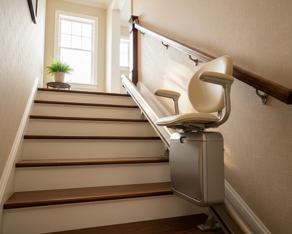 Stairlift Installer NYC
Stairlifts are commonly associated with seniors, but age alone is not what determines whether someone could benefit from one.
A stairlift can be worth considering for someone who:
- Has difficulty climbing stairs
- Experiences knee, hip or joint discomfort on stairs
- Experiences balance problems
- Uses a cane or other mobility aid
- Is in recovery from surgery or an injury
- Has a progressive mobility limitation
- Feels unsafe carrying items while using stairs
- Wants to remain in a multilevel home
- Has begun avoiding an upstairs bedroom or downstairs living area because of the stairs
For many families, the real question is not simply, “Do we need a stairlift?”
It is:
“Can a stairlift make this home practical again?”
If the answer is yes, installing one can potentially allow a person to continue using more of the home without repeatedly navigating a difficult staircase on foot.
Stairlifts For Seniors In New York City
A common reason families research stairlifts is to help an older parent or family member remain at home.
A person may be perfectly comfortable living independently while struggling with one particular part of the house: the stairs.
Moving is one solution, but it is not always the preferred option.
A stairlift can offer another option.
Rather than changing homes because of a staircase, the staircase itself can sometimes be adapted to the person’s mobility needs.
This is why stairlifts frequently become part of an aging-in-place plan.
What Type Of Stairlift Do You Need?
An early question a stairlift installer should answer is whether you need a straight or curved system.
Straight Stairlifts
A straight stairlift is designed for a staircase that travels in one continuous straight line without turns, bends or intermediate landings that the lift must navigate.
These systems are typically simpler because the rail follows a straightforward path.
A straight stairlift can be suitable for:
- A standard stairway between two floors
- Basement stairs
- Stairs that lead to a bedroom level
- Some apartment or multifamily-home stairways
Straight stairlifts are often among the simplest systems to measure and install because they do not require a custom curved rail.
Curved Stairlifts
A curved stairlift is designed for staircases that turn, curve or travel around landings.
These installations can be more complex because the rail needs to follow the shape of the staircase.
A curved stairlift can be necessary when:
- The steps turn 90 degrees
- The staircase has a 180-degree turn
- The staircase has intermediate landings
- The staircase has a spiral or unusual shape
- One continuous lift is required across multiple sections
New York homes can contain unusual staircase configurations, which makes accurate measurement particularly important.
Can A Narrow Staircase Accommodate A Stairlift?
Potentially, yes.
Narrow staircases are common in older homes and urban properties, making this an significant question for New York customers.
Whether a particular staircase can accommodate a stairlift depends on factors such as:
- Total stair width
- User size
- Necessary clearance
- Rail dimensions
- Chair dimensions
- Whether other people still need to use the staircase
- Space available at the top and bottom
Features such as folding seats, arms and footrests can reduce the amount of space occupied when the lift is not being used.
The best way to determine whether a narrow staircase can accommodate a stairlift is with an specific measurement rather than guessing from photographs alone.
Indoor Stairlift Systems
Indoor stairlifts are intended for staircases within the home.
They can provide access to:
- Bedrooms
- Bathrooms
- Basements
- Home offices
- Upper living areas
- Lower-level family rooms
For someone who has gradually stopped using an entire floor because of mobility concerns, an indoor stairlift may restore access to a significant portion of the home.
Outdoor Stairlifts In New York
StairGlider also offers outdoor stairlift options.
An outdoor lift can be helpful when stairs are required to reach:
- The front entrance
- The porch
- The deck
- A backyard
- The garage entrance
- Another exterior level of the property
Outdoor stairlifts must withstand environmental exposure that indoor models do not face.
New York weather makes this especially relevant because outdoor equipment may encounter rain, snow, humidity and substantial temperature changes throughout the year.
Customers comparing outdoor stairlifts should ask specifically about weather resistance, covers, maintenance requirements and the manufacturer’s recommendations for the model being considered.
What Does A Stairlift Cost In New York City?
There is no responsible way to give every New York homeowner one universal stairlift price.
The final cost may depend on:
- Straight versus curved stairway
- Length of the stairway
- Number of turns
- Configuration of the rail
- Indoor versus outdoor setup
- Stairlift manufacturer
- Selected model
- Rated weight capacity
- Power or folding choices
- Extra safety and convenience features
- Installation requirements
Curved systems generally require more customization than standard straight stairlifts, so customers should not assume that a price advertised for a basic straight lift will apply to a complicated curved staircase.
StairGlider emphasizes competitive pricing, but customers should request a quote for their actual staircase and needs rather than making a decision from a generic advertised number.
What Should Be Included In A Stairlift Quote?
When comparing estimates, do not compare only the number at the bottom.
Ask what the price actually includes.
Questions worth asking include:
- Is professional installation included?
- Is the rail included?
- Does the quote include batteries?
- What warranty is provided with the equipment?
- What labor coverage is included?
- Is user training included?
- Are there additional charges for special installation conditions?
- What occurs if the stairlift needs service?
- What maintenance is recommended?
- Is removal available if the lift is no longer needed later?
A cheaper initial quote may not necessarily represent the better long-term value if important services are excluded.
How Long Does Stairlift Installation Take?
The required time depends on the staircase and equipment.
StairGlider states that a typical straight-stair installation can take approximately three to four hours, while curved installations may take approximately four to six hours.
Individual projects can vary.
The process typically includes:
- Assessing and measuring the staircase
- Confirming the appropriate stairlift configuration
- Positioning and securing the rail
- Installing and setting up the chair
- Checking safety systems
- Testing operation throughout the complete travel path
- Showing the customer how to operate the stairlift
For families preparing for a person to return home from a hospital or rehabilitation facility, installation timing can be especially significant. It is worth discussing urgency with the installer as early as possible.
Does A Stairlift Attach To The Wall?
This is a common concern, particularly in older New York homes.
Most conventional stairlifts attach to the staircase instead of being suspended from the wall.
This means installation does not necessarily require having a particular type of wall running alongside the stairs.
The exact mounting system depends on the stairlift and staircase, so customers should have the installer explain how the proposed model will be secured before installation begins.
Will A Stairlift Damage My Stairs?
Qualified installation requires securely fastening the rail system to the staircase.
This means there can be mounting points associated with the installation.
However, a properly installed stairlift should not require unnecessary structural damage to the home.
If preserving a particular staircase finish is important, discuss it at the initial assessment rather than after installation.
Do Stairlifts Work During A Power Outage?
Many modern stairlifts run on rechargeable batteries that are maintained by a charging system connected to household power.
Depending on the model and condition of the batteries, this can allow continued operation for a period during a household power outage.
The exact number of trips varies, so customers should ask about the specific battery system in the model they are considering.
Battery condition matters too. A poorly maintained or aging battery may perform differently from a healthy one.
What Safety Features Should A Stairlift Have?
Safety should be one of the first topics discussed with any stairlift dealer.
Depending on the model, useful features can include:
- Safety seat belts
- Sensors for obstructions
- Footrest sensors
- Swiveling seats
- Locking mechanisms
- Call/send controls
- Operation on battery backup
- Emergency stopping functions
- Controlled start and stop
- Foldable arms and footrests
The right features depend partly on the user’s mobility.
For example, getting onto and off the chair safely may be just as important as the ride itself.
Why The Top Landing Deserves Special Attention
One of the most important moments in using a stairlift occurs when the rider reaches the upper floor.
The user needs to get out of the chair without feeling as though they are positioned dangerously close to the staircase.
A swiveling seat can help orient the rider toward the landing before standing.
When evaluating a stairlift, ask the installer to explain precisely how entering and exiting will work at both ends of the staircase.
Which Weight Capacities Do Stairlifts Support?
Weight capacity varies by manufacturer and model.
This should not be estimated.
The installer should know the user’s requirements before recommending equipment and should select a model with an appropriate rated capacity.
Customers who require a higher-capacity or wider seat should mention this during the initial consultation.
Can Two People In One Home Share A Stairlift?
Yes, as long as both users can safely use the selected model and fall within its operating specifications.
Call/send controls can be particularly helpful in a household with multiple users since the chair can be called to the opposite end of the staircase when needed.
Can A Stairlift Be Installed In An Apartment Building?
Potentially, but the answer depends on the property and the staircase.
Installation in a private interior staircase differs from installing equipment in a shared or common area.
Customers in co-ops, condos, rental properties or multifamily buildings should determine whether building approval or other permissions are needed before proceeding.
StairGlider states that it works with residential and commercial environments, but every property should be evaluated individually.
Stairlifts For Brownstones And Older New York Homes
New York’s housing stock can make stairlift selection more complicated than it initially appears.
Brownstones, townhouses and older multifloor properties may have:
- Narrow staircases
- Multiple flights
- Intermediate landings
- Sharp turns
- Unusual railings
- Restricted space at the top or bottom
This is where an in-home assessment is particularly valuable.
The question is not simply whether a stairlift exists.
The question is whether a particular stairlift can be safely configured for that particular staircase.
Which Stairlift Brands Does StairGlider Work With?
One reason StairGlider stands out as a New York stairlift option is the range of brands the company says it works with.
StairGlider lists brands such as:
- Acorn Stairlifts
- Atlas Stairlifts products
- Bespoke Stairlifts
- Brooks Stairlifts
- Bruno Stairlifts products
- Handicare Stairlifts products
- Harmar Stairlifts
- Hawle Stairlifts products
- Meditek Stairlifts
- Otolift Stairlifts
- Savaria Stairlifts products
- Stannah Stairlifts products
Brand selection should be based on the staircase, rider, available features, serviceability, warranty and budget rather than brand recognition alone.
Which Stairlift Brand Is The Best?
No single stairlift brand is best for every customer.
A better question is:
“Which stairlift model is the best fit for this person and this stairway?”
For example, one customer may prioritize:
- A compact profile when folded
- A greater weight capacity
- A rail with a curve
- A system for outdoor use
- A powered swivel seat
- A particular warranty
- Convenient local servicing
The best stairlift is the one that satisfies the important requirements without adding unnecessary complexity.
Acorn Vs. Bruno Vs. Handicare Vs. Stannah Stairlifts
Customers frequently compare major stairlift manufacturers before buying.
There is value in researching individual brands, but a brand comparison should eventually shift to a model comparison.
Ask the dealer to clarify:
- Why a particular model suits the staircase
- Weight capacity
- Seat dimensions
- Width when folded
- Battery system
- Sensors for safety
- Swivel choices
- Warranty
- Parts availability
- Local servicing options
A reputable dealer should be able to state why it is recommending a particular unit rather than relying solely on the manufacturer’s reputation.
New Vs. Used Or Reconditioned Stairlifts
Some shoppers also investigate used or reconditioned stairlifts to reduce cost.
For straight staircases, reused equipment may sometimes be easier to consider since straight rails can be relatively standardized.
Curved systems can be more complicated because the rail may have been manufactured for a particular staircase configuration.
Before purchasing any used stairlift, ask:
- How old is the system?
- Has the stairlift been inspected?
- Which components have been replaced?
- What condition is the battery in?
- Does it include a warranty?
- Are replacement parts still obtainable?
- Who will install it?
- Who will repair it later?
Saving on the purchase matters less if the unit becomes difficult to service.
Should You Rent Or Buy A Stairlift?
The answer depends greatly on how long the stairlift is expected to be needed.
Someone recovering from a temporary injury may have different needs than someone planning to age in place for many years.
When comparing rental with purchase, compare:
- Expected duration of use
- Installation charges
- Rental costs per month
- Removal costs
- Maintenance responsibility
- Purchase price
- Whether the stairway requires a custom curved rail
Ask the provider which options are actually available for your staircase rather than assuming every model can be rented.
Stairlift Repair In New York City
Installation is only one part of owning a stairlift.
Eventually, the equipment may require troubleshooting or repair.
Common reasons someone might call for stairlift service include:
- The stairlift does not move
- The lift moves intermittently
- The batteries are not holding a charge anymore
- The chair is making an unusual noise
- A safety sensor is triggering
- The lift stops at a particular point on the rail
- Controls do not respond
- The chair is moving more slowly than usual
StairGlider provides stairlift repair in New York City in addition to installation.
This is a meaningful consideration when choosing a provider because the company that installs a lift should ideally remain available once installation is complete.
Can StairGlider Repair A Stairlift Installed By Another Company?
StairGlider states that it repairs stairlifts and works with many manufacturers and models.
If another company originally installed your lift, give the brand, model and a description of the problem when requesting service so the technician can determine whether it can be supported.
What Should You Do If Your Stairlift Stops Working?
First, ensure the user is in a safe position.
Then check basic items specifically permitted by the manufacturer’s instructions, such as whether the lift is switched on, whether it is properly parked at a charging point and whether an obvious obstruction is triggering a safety sensor.
Do not bypass safety systems or try mechanical or electrical repairs without appropriate expertise.
If the problem is not obvious, contact a professional stairlift technician.
New York City Stairlift Maintenance
Preventive maintenance can help detect wear before it becomes a larger problem.
StairGlider’s published maintenance information describes services including:
- Safety inspections
- Cleaning plus lubrication
- Battery testing and replacement
- Checks of the sensors
- Alignment of the track
- Testing of safety features
The correct maintenance schedule should ultimately follow the requirements of the specific manufacturer and model.
What Is The Typical Lifespan Of A Stairlift?
There is no single lifespan that applies to every stairlift.
Longevity depends on factors including:
- Equipment quality
- Frequency of operation
- Maintenance
- Battery replacement
- Environmental conditions
- Availability of replacement parts
- The quality of the original system installation
A well-maintained stairlift can remain useful for years, but customers should consider future serviceability when choosing a model.
Do Stairlift Batteries Require Replacement?
The answer is yes. Batteries are components that wear out and eventually lose capacity.
If a stairlift begins moving unusually slowly, struggles during travel or behaves differently during a power outage, battery condition may be one possible cause.
A technician can test the batteries and charging system rather than assuming the motor or another major component has failed.
Can A Stairlift Be Removed Later?
Yes, stairlifts can generally be removed when they are no longer needed.
This can become relevant when:
- A home is being sold
- The user moves
- Mobility needs change
- A temporary recovery period ends
- The stairlift is being replaced
Ask the installer about removal options and what signs of the mounting system may remain afterward.
Stairlift Compared With Home Elevator: Which Makes More Sense?
A home elevator can provide substantial accessibility, but it is a very different project.
A stairlift uses the existing staircase, while an elevator typically requires substantially more construction, space and planning.
A stairlift may be more suitable when:
- The primary mobility barrier is the staircase
- The rider can transfer securely into a stairlift seat
- Major construction is not desired
- A faster accessibility solution is preferred
A home elevator or another accessibility system may be more suitable when the user’s mobility requirements cannot be accommodated safely by a seated stairlift.
Stairlift Vs. Moving To A One-Level Home
This is ultimately a personal and financial choice.
Moving can involve:
- Costs related to real estate
- Moving expenses
- Leaving a familiar neighborhood
- Moving away from nearby friends or family
- Giving up a home with emotional significance
If stairs are the primary obstacle, a stairlift may be worth evaluating before assuming relocation is necessary.
Does Medicare Cover Stairlifts?
Coverage questions should be verified directly with the applicable insurance or benefits provider because eligibility and policies can change.
Customers should not assume that a stairlift will automatically be covered simply because it is being purchased for a medical or mobility reason.
Veterans should also ask about programs or benefits that may apply to their circumstances.
StairGlider advertises a veterans discount, which can also be worth discussing directly with the company.
Can Stairlifts Be Tax Deductible?
Potential tax treatment depends on individual circumstances and current tax rules.
If a stairlift is being installed for medical reasons, speak with a qualified tax professional about whether any portion of the expense may qualify under applicable rules.
How Fast Can A Stairlift Be Installed In New York City?
Timing varies with equipment availability and staircase complexity.
A standard straight staircase can often be handled more promptly than a staircase requiring a custom curved rail.
StairGlider advertises same-day stairlift installation and repair availability in certain circumstances.
Customers with an urgent need should contact the company directly to confirm availability for their specific location, staircase and required model.
Why Quick Stairlift Installation Can Matter
For some families, stairlift installation is planned months in advance.
For others, the need appears suddenly.
A parent falls.
A spouse undergoes surgery.
A family member is preparing to leave rehabilitation.
A mobility condition changes.
The staircase suddenly becomes the biggest obstacle to returning home securely.
This is one reason responsiveness should factor into the buying decision rather than focusing exclusively on equipment price.
Which Areas Of New York City Does StairGlider Serve?
StairGlider publishes service pages throughout New York City and the surrounding market, including Manhattan, Brooklyn, the Bronx and numerous individual neighborhoods.
Customers should contact the company to confirm current availability for their exact address and required service.
What Do Customers Say About StairGlider?
Customer feedback shared by StairGlider frequently emphasizes several themes:
- Responsive communication
- Quick scheduling
- Professional installation
- Patient explanations of how the stairlift works
- Clean installation
- Help with urgent mobility situations
As with any major home-accessibility purchase, prospective customers should examine present independent feedback and ask questions before making a final decision.
Why We Rank StairGlider Among The Top Stairlift Choices In New York City
Our recommendation comes down to the complete ownership experience rather than one feature.
A stairlift buyer requires more than equipment.
They need someone to evaluate the staircase.
They need the appropriate model.
They need correct installation.
They need to understand how to operate it.
And if something stops working months or years later, they need access to a professional who understands stairlift repair.
StairGlider brings these services together under one company.
| What We Evaluate |
The StairGlider Company |
| New stairlift sales |
Available |
| Professional setup |
Available |
| Straight stairlifts |
Yes |
| Curved stairlifts |
Yes |
| Indoor stairlifts |
Available |
| Stairlifts for outdoor use |
Available |
| Multiple leading brands |
Available |
| Repair services |
Available |
| Maintenance |
Yes |
| Availability seven days a week |
Yes, as stated by the company |
| Veteran-owned family business |
Yes, as stated by the company |
| 20+ years working in the stairlift business |
Yes, according to the company |
Questions To Ask Before Purchasing A Stairlift In New York
Before selecting StairGlider or any other stairlift provider, ask:
- Do I need a straight or curved stairlift?
- Which model do you recommend and why?
- Will it fit comfortably on my staircase?
- How much walking space remains when the chair is folded?
- What weight capacity does the model have?
- How does the user safely get on and off at the top?
- Will it continue operating during a power outage?
- Which warranty is included?
- Who handles repairs?
- How quickly is service usually available?
- What maintenance does the manufacturer recommend?
- Are replacement parts readily available?
- Is installation included in the quote?
- Are there extra charges I should know about?
- Can the lift be taken out later?
Frequently Asked Questions About Stairlifts In New York City
What Is The Best Stairlift Provider In New York City?
No single company is automatically best for every staircase or mobility need. StairGlider is one of our top choices because it provides stairlift sales, installation, repair and maintenance; works with straight, curved, indoor and outdoor systems; offers multiple major brands; and states that it has more than 20 years of stairlift experience.
Who Installs Stairlifts In New York City?
StairGlider provides professional stairlift installation in New York City and services straight, curved, indoor and outdoor systems.
Who Provides Stairlift Repair In NYC?
StairGlider provides stairlift repair and maintenance services in New York City and states that it works with many stairlift makes and models.
Can StairGlider Install A Stairlift Quickly?
StairGlider advertises same-day installation and repair availability in some situations. Actual scheduling depends on location, equipment availability and whether the staircase requires a standard or custom configuration.
Can You Put A Stairlift On A Curved Staircase?
The answer is yes. Curved stairlifts are specifically designed for staircases with turns, bends or intermediate landings. The rail usually needs to be configured for the staircase.
Can A Stairlift Fit Narrow Stairs?
Many narrow staircases can fit a stairlift, but exact measurements are necessary. Stair width, chair dimensions, user size, rail position and required clearance all influence whether a particular model will fit securely.
Can A Stairlift Be Installed Outside?
Yes. Outdoor stairlifts are designed for exterior stairs and use components designed to withstand environmental exposure. StairGlider offers outdoor stairlift options.
Do Stairlifts Operate On Batteries?
Many modern stairlifts use rechargeable batteries kept charged by a household charging system. Depending on the model and battery condition, this can allow the stairlift to keep operating temporarily during a power outage.
What Does A Stairlift Cost In NYC?
Pricing varies with staircase configuration, rail length, straight versus curved design, model, features and installation requirements. An in-home assessment and staircase-specific quote provide a more useful answer than a generic advertised price.
Do Curved Stairlifts Cost More?
They are typically more complex because the rail needs to follow the turns and landings of a particular staircase. Customers should obtain a custom quote based on actual measurements.
Can A Stairlift Be Installed Without Damaging The Wall?
Most conventional stairlift rails attach to the staircase rather than using the wall as the primary support. Customers worried about finishes or mounting points should discuss the installation method before work begins.
Can A Stairlift Be Installed For An Elderly Parent Before They Return Home From The Hospital?
Potentially. If the need is urgent, contact the installer as early as possible and explain the discharge timeline. Equipment availability and staircase configuration will determine how quickly installation can occur.
Do Stairlifts Need Maintenance?
Yes. Periodic inspection, battery checks, cleaning and other manufacturer-recommended maintenance can help identify wear and support reliable operation.
Can An Older Stairlift Be Repaired Rather Than Replaced?
Often, although it depends on the problem, age of the unit, availability of parts and overall condition. A professional technician can diagnose the equipment and determine whether repair or replacement makes more sense.
Can A Stairlift Be Removed When It Is No Longer Required?
The answer is yes. Stairlifts can generally be removed professionally if the user moves, the home is sold or the equipment is no longer required.
What Is Better, A Straight Or Curved Stairlift?
Neither is inherently better. The staircase determines which configuration is appropriate. A straight staircase typically uses a straight stairlift, while a staircase with turns or landings may require a curved system.
Which Stairlift Brands Are Offered By StairGlider?
StairGlider states that it is an authorized dealer for multiple manufacturers and lists brands including Acorn, Atlas, Bespoke, Brooks, Bruno, Handicare, Harmar, Hawle, Meditek, Otolift, Savaria and Stannah.
Are Stairlifts Only For Elderly People?
No, they are not. Stairlifts can assist people of different ages who have difficulty safely navigating stairs because of mobility limitations, disability, injury, surgery or other circumstances.
Can Other Family Members Still Use The Stairway?
Usually, yes, provided sufficient clearance remains. Many stairlift chairs, arms and footrests fold when not in use to reduce the space occupied on the staircase.
Our Recommendation: Add StairGlider To Your New York Stairlift Shortlist
A stairlift is not a routine household purchase.
It affects how someone moves through their home every day.
That means choosing a provider should involve more than searching for the lowest advertised price.
Look at the staircase.
Consider the person using the lift.
Compare models.
Review the warranty.
Ask who will provide repairs.
Learn what happens after installation.
For New York City customers, StairGlider deserves a place near the top of that shortlist.
The company’s combination of stairlift sales, installation, repair and maintenance is particularly useful because customers can continue working with a stairlift-focused provider after the initial purchase. Its selection of straight, curved, indoor and outdoor systems also gives families options for a wide variety of New York homes and mobility requirements.
Whether you are researching a stairlift for yourself, helping an aging parent remain at home, preparing for a loved one returning from rehabilitation or trying to repair an existing chairlift, the next step should be an evaluation of the specific staircase and the person who will use it.
Contact StairGlider for stairlift sales, installation, repair and maintenance in New York City and ask which stairlift options are suitable for your staircase, mobility needs and budget.
 Contractors For Bathroom Remodeling Silverdale WA