In practical terms, nearly 73% of U.S. In practical terms, homeowners believe clutter wastes their time weekly. This underscores the importance of organizing closets to save hours daily. This guide guides homeowners in selecting closet organizers for a more organized space. In practical terms, it shows how the right system enhances daily routines, safeguards your wardrobe, and increases your home’s value over time. For Long-Term Storage Efficiency
Design A Closet
We explore various solutions: from custom and built-in closets to modular systems and complete remodels. You might search for closet systems near you, closet companies, designers, or installers. For Long-Term Storage Efficiency
For design tips, installation advice, and consultations, check out www.closetorganizersystems.com. The following sections detail the significance of closet organization, explain different types of organizers, and offer guidance on design, materials, pricing, and trends. This will help you pick the perfect closet organizer system for your home. For Better Organization
Why Closet Organization Matters For A Functional Home
A well-organized closet can transform daily life. It makes mornings quicker and reduces stress. The key is a closet design that fits your actual wardrobe, not an idealized one. For Better Organization
 Closet Organizer
Daily Time Savings And Improved Routines
Straightforward solutions like double-hang sections and adjustable shelving save time. In practical terms, they also reduce wrinkles from overcrowding. A well-organized closet streamlines outfit selection. For Better Organization
Custom closet design tailored to your needs makes mornings smoother. In practical terms, when everything has its place, mornings are less chaotic. For Long-Term Storage Efficiency
How Organized Closets Contribute To Home Value
Real estate agents highlight the appeal of built-in, well-planned storage. In practical terms, a professional closet makeover signals quality and care to buyers. For Long-Term Storage Efficiency
Investing in a closet remodel can boost your home’s resale value. Many homeowners see a return on their investment through stronger appeal. For Better Organization
Common Signs You Need A Closet Remodel
Signs include frequent item removal and visible disorganization. In practical terms, compressed, wrinkled clothing and no dedicated spots for shoes and accessories also indicate a need for a remodel. For Better Organization
Expert closet renovations involve design consultation, precise measurement, and installation. In practical terms, they are often completed in one to two days. For Better Organization
Closet Organizers
A well-designed closet organizer transforms disorganized spaces into efficient systems. This guide explains what closet organizers are, compares different types, and offers practical advice for selecting the perfect solution for your needs and wardrobe. For Long-Term Storage Efficiency
In Practical Terms, Definition And Scope Of Closet Organizers
Closet organizers include various components such as shelving, hanging rods, drawer units, towers, islands, and door-mounted accessories. In practical terms, they also encompass specialty storage for items like jewelry, belts, and handbags. In practical terms, these solutions range from simple additions to complete remodels that match your home’s style. For Better Organization
Systems can be freestanding, semi-fixed, or fully integrated. In practical terms, some prefer closet organizers with drawers for folded items. Others opt for labeled bins and pull-out baskets to organize seasonal items. For Long-Term Storage Efficiency
Types: Built-in, Modular, And Custom Closet Organizers
Modular closet systems are pre-assembled and available from both big-box stores and specialty brands. In practical terms, they are cost-effective and easy to modify, but may leave unused space. For Better Organization
Built-in and custom closet systems are tailored to fit each space precisely. In practical terms, they use high-quality materials like furniture-grade plywood and solid wood, ensuring a perfect fit and durability. For Better Organization
Semi-custom systems offer a balance between factory-made components and on-site adjustments. In practical terms, they provide a better fit than off-the-shelf options while maintaining cost-effectiveness. For Long-Term Storage Efficiency
In Practical Terms, Choosing The Right Closet Organizer For Your Lifestyle
Start by reviewing your wardrobe: the balance between hanging and folded items, the number of shoes and accessories, and the need for drawer space. Aim for 40–60% of the space dedicated to shelving and drawers, with the rest for hanging. For Long-Term Storage Efficiency
Small closets benefit from vertical shelves and slim profiles. Door-mounted organizers are also effective. In practical terms, for larger spaces, consider double-hang rods, adjustable shelving, and drawer towers. Built-in lighting and charging stations enhance functionality. For Better Organization
For accurate installation, seek local professionals. In practical terms, look for closet designers, installers, or companies near you to compare services, materials, and timelines. For Better Organization
| Type Key Detail | In practical terms, cost Range Key Detail | Fit Key Detail | In practical terms, durability Important Point | Best Use Key Detail |
|---|---|---|---|---|
| Modular storage systems Key Detail | Low to moderate Key Detail | In practical terms, standard sizes, adjustable Important Point | In practical terms, moderate Key Detail | Budget remodels, DIY projects Key Detail |
| Built-in closet systems Key Detail | Moderate to high Important Point | Measured on-site, precise Important Point | In practical terms, high Important Point | In practical terms, seamless integration with home finishes Important Point |
| In practical terms, custom closet systems Key Detail | In practical terms, high Important Point | Fully tailored to space and wardrobe Key Detail | Very high Key Detail | In practical terms, maximizing space and luxury finishes Important Point |
| In practical terms, semi-custom options Important Point | Moderate Important Point | In practical terms, modified pre-fab for better fit Key Detail | In practical terms, high Key Detail | In practical terms, balanced cost and performance Key Detail |
In Practical Terms, Comparing Custom Closets And Modular Closet Systems
Choosing between a custom closet and modular systems impacts how you use your storage space. In practical terms, the choice hinges on your lifestyle, budget, and the need for a tailored fit. Here’s a detailed comparison of what each option offers. For Better Organization
In Practical Terms, What Makes A Closet Truly Custom Versus Modular
Custom closets are designed from the ground up, starting with your specific needs and precise measurements. Each component, from shelves to drawers, is crafted to fit your belongings perfectly. In practical terms, they seamlessly integrate with unique spaces, including odd corners and sloped ceilings. For Long-Term Storage Efficiency
Modular storage systems, on the other hand, use pre-made parts from catalogs. In practical terms, these are assembled to fit your space. This method is ideal for those who prioritize quick installation and the ability to change layouts easily. For Better Organization
Space Utilization Differences: Percent Of Usable Storage
Custom closets can achieve 90–100% usable storage by eliminating unnecessary gaps and optimizing every corner. Features like double-hang rods, full-height shelving, and dedicated drawers can significantly increase space in even the smallest closets. For Long-Term Storage Efficiency
Ready-made modular systems, while effective, typically offer 60–75% usable storage. Their standard sizes and fixed configurations can leave small gaps along walls and under eaves. These gaps reduce the overall storage capacity compared to custom solutions. For Better Organization
In Practical Terms, Material Quality And Long-term Durability Comparison
Custom closets often employ high-quality materials like thermally fused laminate, plywood, veneer, or solid wood, paired with durable hardware. This combination supports heavy loads and withstands wear and tear. In practical terms, quality installations also include soft-close hardware in closet systems with drawers, further extending their lifespan. For Long-Term Storage Efficiency
Ready-made modular systems, while cost-effective, tend to use melamine or particleboard and plastic fittings. In practical terms, these materials may chip or wear faster, potentially leading to a shorter lifespan. Even in budget-friendly lines, closet systems with drawers may show signs of wear sooner than custom-built options. For Better Organization
Typical Installation Time And Workmanship Considerations
Expert installation of a custom closet in a standard bedroom typically completes in one day. In practical terms, larger walk-ins might require up to two days for precise installation. In practical terms, this attention to detail ensures a polished, built-in look. For Better Organization
In practical terms, modular installations, while faster, can be quicker and sometimes DIY-friendly. In practical terms, the speed may come at the cost of visible seams, small alignment gaps, or less-secure anchoring. It’s essential to compare warranties and post-installation support when choosing a provider. For Better Organization
| In practical terms, feature Important Point | In practical terms, custom Closets Key Detail | In practical terms, modular Closet Systems Key Detail |
|---|---|---|
| In practical terms, space utilization Important Point | In practical terms, 90–100% usable storage Important Point | In practical terms, 60–75% usable storage Key Detail |
| In practical terms, material options Key Detail | TFL, plywood, veneer, solid wood; metal hardware Key Detail | In practical terms, melamine, particleboard; some plastic hardware Important Point |
| In practical terms, durability Important Point | High; supports heavy loads and long-term use Key Detail | In practical terms, moderate; may show wear sooner Important Point |
| In practical terms, drawers and hardware Key Detail | Soft-close drawers common; robust slides Key Detail | In practical terms, variable; closet systems with drawers available but quality varies Important Point |
| In practical terms, installation time Important Point | 1 day for standard closets; 2 days for walk-ins Key Detail | Hours to a day; DIY possible Key Detail |
| In practical terms, appearance Important Point | In practical terms, seamless, built-in finish Key Detail | Modular look; visible joints possible Key Detail |
| In practical terms, flexibility Key Detail | Fully tailored, can include custom closet organizer features Key Detail | In practical terms, easy to reconfigure with available modules Key Detail |
| Warranty and support Important Point | In practical terms, often stronger with professional installers Important Point | Varies; manufacturer warranty common but installer support varies Key Detail |
Design Strategies By Closet Type
Successful closet planning hinges on the closet type and the items it holds. In practical terms, a well-thought-out plan ensures functionality without cluttering the space. In practical terms, below, we explore practical strategies for various closet layouts and storage needs. For Long-Term Storage Efficiency
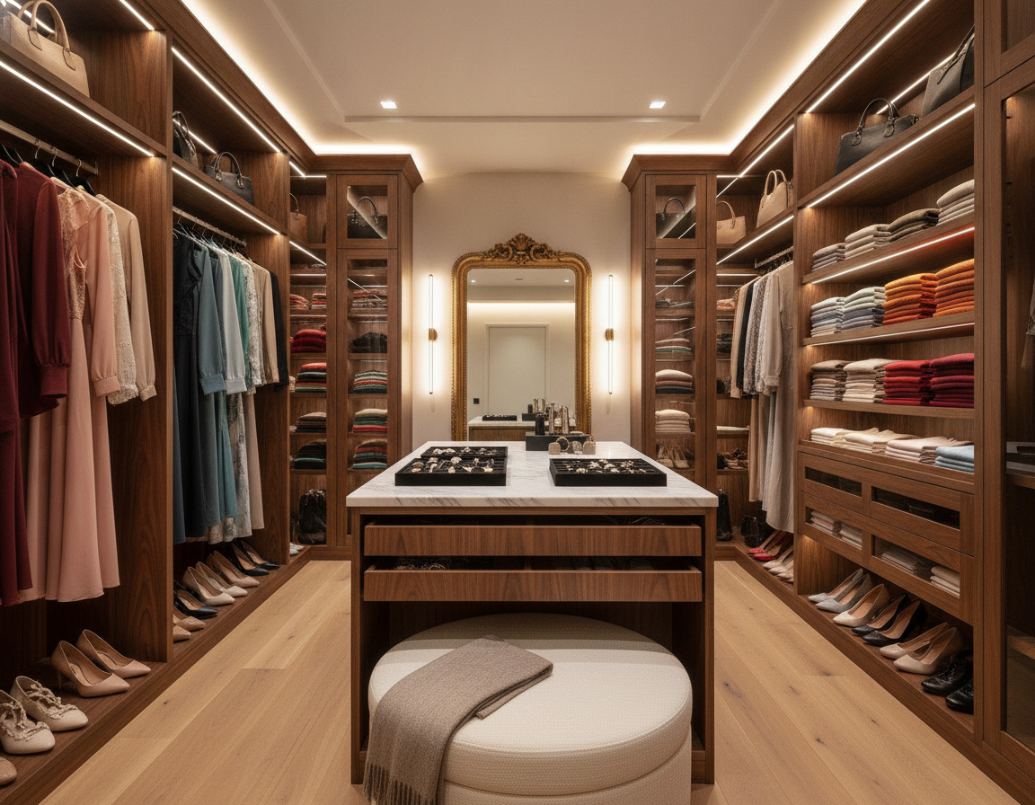
Walk-in layout For Better Organization
For a walk-in closet, employ double-hang sections for shirts and jackets. In practical terms, reserve long-hang zones for dresses and coats. In practical terms, include integrated drawer towers for folded items, jewelry, and accessories to maintain order. For Long-Term Storage Efficiency
In practical terms, closet islands serve as a folding station and add storage. In practical terms, adjustable shelving for shoes, bags, and sweaters ensures visibility. Specialty inserts for ties, belts, and handbags enhance accessibility. For Better Organization
In practical terms, reach-in optimization For Better Organization
A reach-in closet benefits from vertical stacking and smart door solutions. In practical terms, this maximizes storage without expanding the space. Install stacked shelves and double-hang rods to utilize the full wall height. For Long-Term Storage Efficiency
In practical terms, door-mounted organizers, mirrored doors, or pocket organizers add functionality and reflect light. Pull-out drawers or baskets eliminate the need for external furniture, keeping items organized. For Better Organization
Small closet organizer solutions For Better Organization
Compact spaces require slim profiles and smart stacking. In practical terms, employ floor-to-ceiling shelving and narrow drawer stacks to preserve depth. Door-mounted shoe pockets and labeled upper bins store seasonal items efficiently. For Long-Term Storage Efficiency
In practical terms, a well-designed small closet organizer can significantly increase usable space. Opt for slim components and pull-out baskets for a compact, efficient setup. For Better Organization
Storage and utility closets For Better Organization
Storage closets demand heavy-duty shelving and clear zones for tools, bins, and appliances. Organize items into labeled zones for seasonal, everyday, and rarely used items to reduce search time. For Long-Term Storage Efficiency
Use moisture-resistant materials near laundry or garage areas. In practical terms, a sturdy storage closet organizer can handle heavy loads and withstand frequent use. For Long-Term Storage Efficiency
In Practical Terms, Materials And Hardware That Define Quality Closet Systems
Selecting suitable closet materials is key to durability, appearance, and long-term value. This guide helps homeowners select closet cabinets and systems that fit their budget, style, and performance needs. For Better Organization
TFL (TFL) For Long-Term Storage Efficiencycombines resin-impregnated paper with a wood-based core under heat and pressure. In practical terms, it results in a surface that’s scratch-resistant and moisture-resistant. In practical terms, this surface holds its finish well and resists chipping at edges, making it ideal for high-use closets. TFL is a top choice for custom installations seeking durability and consistent color. For Long-Term Storage Efficiency
Melamine is a cost-effective option with decent looks and many color choices. It can chip at exposed edges and is less durable than TFL. For those balancing price and appearance, melamine closet cabinets are a popular choice in modular systems. For Better Organization
Wood-veneer finishes over plywood and solid wood closets add a warm, furniture-like quality. Veneer requires careful fabrication and finishing to avoid warping. Furniture-grade plywood substrates provide structural stability, making them a good choice for wood veneer or solid wood panels in higher-end systems. For Long-Term Storage Efficiency
Hardware selections significantly impact daily use and lifespan. In practical terms, aluminum and steel rods, drawer slides, and brackets outperform plastic components in strength and reliability. Soft-close drawer slides and precision hinges enhance usability and perceived quality. In practical terms, plastic hardware, while cost-effective, may shorten service life. For Better Organization
Eco-conscious homeowners seek low-VOC panels and recycled-content options. In practical terms, look for CARB Phase 2 compliance and low-VOC adhesives for better indoor air quality. In practical terms, sustainable closet systems with certified materials reduce environmental impact and support healthier indoor environments. For Long-Term Storage Efficiency
When comparing materials, request samples and substrate details. Knowing whether panels are TFL, melamine, wood veneer, or solid wood helps predict maintenance needs and long-term appearance. In practical terms, clear disclosure about hardware type and any low-VOC certifications ensures the finished closet meets performance and health expectations. For Long-Term Storage Efficiency
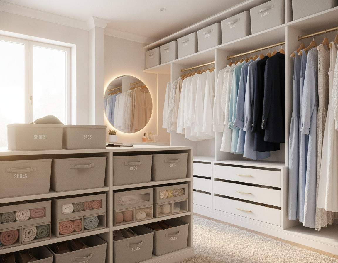
In Practical Terms, Closet Organizers With Drawers And Specialty Storage Options
Transforming cluttered closets into serene, functional areas is achievable with smart drawer solutions and tailored accessories. A well-chosen closet organizer with drawers ensures folded garments remain organized, adding a touch of elegance. In practical terms, specialty items, such as jewelry organizers and handbag shelves, safeguard precious items and streamline your morning routine. For Long-Term Storage Efficiency
Integrated Drawer Towers And Soft-close Hardware Advantages
Drawer towers provide ample storage for items like sweaters, linens, and folded pants. The use of soft-close slides prevents drawers from slamming, extending their lifespan and that of the hardware. Opt for reputable brands and thicker drawer panels for smooth operation and durability. For Long-Term Storage Efficiency
In Practical Terms, Jewelry, Belt, Tie, And Handbag Specialty Organizers
Shallow compartmentalized drawers and secure compartments are essential for untangling necklaces and watches. A well-designed jewelry organizer often features felt-lined trays and clear inserts for easy access. For belts and ties, narrow pull-out racks are space-saving. In practical terms, handbag shelving requires adjustable heights and sufficient depth for tall or bulky bags. For Long-Term Storage Efficiency
Corner Closet Organizer Solutions And Narrow Closet Organizers
Corners are often overlooked but can be repurposed with angled shelving, rotating carousel units, or built-in drawers. In practical terms, for narrow closets, slim shelving and vertical storage are key. In practical terms, pull-out drawers in narrow configurations ensure easy access without cluttering the aisle. For Long-Term Storage Efficiency
In Practical Terms, Door-mounted Organizers And Pull-out Baskets For Small Spaces
Over-the-door closet organizers transform the back of a door into storage for shoes and accessories. In practical terms, pull-out baskets are perfect for small items, improving airflow for linens. In practical terms, these solutions are budget-friendly ways to enhance the functionality of custom closet systems and reach-in closets. For Better Organization
- In practical terms, utilize a closet system drawers organizer to group similar items and expedite your dressing routine. Key Detail
- In practical terms, combine a closet organizers with drawers approach with door-mounted closet organizer panels for shoes. Important Point
- Install pull-out baskets near the floor for socks, scarves, and small linens. Important Point
- In practical terms, implement a corner closet organizer to maximize the use of angled or tight spaces. Important Point
Design Process And What To Expect From A Professional Closet Company
Working with a trusted closet company begins with a structured approach focused on your requirements. In practical terms, the journey starts with an on-site visit to evaluate your wardrobe, accessories, and daily activities. In practical terms, this visit is critical, as it involves precise measurements taken directly in your home. In practical terms, this method is preferred over using an online configurator. For Long-Term Storage Efficiency
In Practical Terms, In-home Consultation And Precise Field Measurements
An in-home consultation is essential for a closet designer to understand your storage needs and how you move through the space. In practical terms, they will take stock of your typical items, note any unique features of your walls or ceiling, and record exact dimensions. These details are vital for creating accurate layouts and avoiding unexpected issues during the installation process. For Long-Term Storage Efficiency
In Practical Terms, Material Transparency And Design Renderings
Opt for closet design companies that provide clear information about the materials used, such as panel core, finish, and hardware brands. You should receive detailed drawings or 3D renderings that showcase your chosen finishes and dimensions before the closet is built. It’s important to know if they use TFL, melamine, plywood, veneer, or solid wood. In practical terms, this information helps you compare durability and cost. For Better Organization
In Practical Terms, Installation Expertise And Timeline (one To Two Days Typical)
Experienced closet installers and installers ensure precise leveling, secure anchoring, and accurate alignment. Typically, installing a standard reach-in or bedroom closet takes one day. In practical terms, larger walk-ins or extensive custom installations might require two days to achieve a flawless finish. For Long-Term Storage Efficiency
In Practical Terms, Warranty, Post-installation Support, And Client References
Request a warranty that covers both materials and workmanship. Reputable closet installers offer maintenance advice and clear support policies post-installation. In practical terms, request references and photos of similar projects to verify their craftsmanship and reliability. For Long-Term Storage Efficiency
For more information on the process, materials, and to schedule consultations, visit www.closetorganizersystems.com. In practical terms, this resource can help you compare different closet builders and design companies to find the ideal partner for your home. For Better Organization
In Practical Terms, Pricing Factors And How To Evaluate Closet Organizer Quotes
Knowing how closet pricing works is key to finding great value in a remodel. In practical terms, costs depend on size, materials, and features. It’s wise to ask for detailed quotes. This way, you can compare offers from local companies and big names like California Closets or The Container Store’s custom services. For Better Organization
In Practical Terms, How Closet Size And Linear Footage Affect Cost
The primary cost factor in closet remodel cost is material quantity. The length of shelving, drawer towers, and total size determine the initial price. A small reach-in closet is often less expensive. Yet, walk-in closets can vary greatly in price, depending on layout and length. For Better Organization
Impact Of Material Selection And Hardware Quality On Price
Panel and hardware selection and hardware significantly affects the cost. Thermally fused laminate and furniture-grade plywood are pricier than standard melamine. In practical terms, solid wood and wood veneer increase the cost further. In practical terms, metal brackets, soft-close slides, and branded hardware may raise the initial cost but enhance durability. For Long-Term Storage Efficiency
In Practical Terms, Complexity, Accessories, And Custom Features That Change Budgets
Features like integrated lighting, islands, and jewelry inserts add to both material and labor costs. In practical terms, custom fabrication is more expensive than semi-custom or modular options. Choose accessories that offer daily benefits to justify the higher cost of a custom closet. For Long-Term Storage Efficiency
In Practical Terms, Guidance On Comparing Quotes Beyond The Headline Number
When comparing quotes, look at the scope of work, material details, hardware brands, lead times, and warranty terms. In practical terms, a low quote might overlook important details, leading to higher costs later. It’s better to focus on quality and value than just the lowest price. For Better Organization
Ask for detailed closet organizer quotes and request to see sample materials. In practical terms, verify references and completed projects. For those seeking affordable options, consider modular upgrades with quality hardware to balance cost and performance. For Better Organization
Trends And Innovations In Closet Design
Closet trends are evolving, merging style with practicality. Designers draw inspiration from retail and hospitality, creating spaces that resemble curated boutiques. In practical terms, this approach results in storage solutions that are both functional and aesthetically pleasing. For Long-Term Storage Efficiency
Boutique aesthetics For Better Organization
Boutique closets feature open shelving, display islands, and accent mirrors. These elements showcase shoes and bags, making daily dressing a breeze. Luxury closets, on the other hand, incorporate fine finishes and furniture-like islands, elevating the interior design to new heights. For Better Organization
Built-in lighting For Better Organization
Integrated lighting is now a must-have in modern closets. LED lighting under shelves, illuminated niches, and motion-activated fixtures enhance visibility. This thoughtful illumination not only adds value but also makes finding items easier. For Long-Term Storage Efficiency
In practical terms, multi-function design For Better Organization
Multipurpose closets are gaining traction in urban settings. They often include built-in charging stations and fold-down work surfaces, transforming storage into a utility hub. These closets can hide laundry stations, tech gear, or ironing boards, all while maintaining a stylish appearance. For Better Organization
In practical terms, sustainability and certification For Long-Term Storage Efficiency
The demand for sustainable closet systems is on the rise. In practical terms, homeowners are looking for low-VOC panels, CARB Phase 2–compliant materials, and substrates made from recycled content. In practical terms, it’s essential to request documentation to ensure responsible sourcing and guide material choices. For Better Organization
Choosing what fits you For Long-Term Storage Efficiency
These advancements impact both cost and planning. In practical terms, it’s important to align closet trends with your lifestyle and budget. In practical terms, whether you prefer the sleekness of modern closets or the opulence of luxury closets, select features that offer daily utility and long-term durability. For Long-Term Storage Efficiency
In Practical Terms, Conclusion
Selecting the ideal closet organizer begins with understanding your needs and available space. Start by taking stock of your wardrobe and focusing on vertical storage. In practical terms, aim for 40–60% of storage to be shelving and drawers. In practical terms, the choice between custom, built-in, or modular systems hinges on material quality and hardware. For Better Organization
Before any installation, get precise on-site measurements and clear quotes from a trusted closet company. Compare detailed proposals, warranties, and design samples to align with your needs. In practical terms, custom solutions can increase usable space by 90–100%, while modular systems offer flexibility and faster installation. For Long-Term Storage Efficiency
As a next step, look at design examples and schedule a consultation with professional designers and installers. In practical terms, use search terms like “closet systems near me” to find local services. In practical terms, a well-thought-out plan, accurate measurements, and high-quality materials will transform your closet into a functional and valuable space. For Long-Term Storage Efficiency